User Manual
Doepfer A-101-2 Vactrol LPG
Intro
User Interface
In Use
What the Heck are Vactrols?
Credits
The Doepfer A-101-2 Vactrol LPG is a vactrol based combination of a 12 dB Low Pass filter (LP) and VCA. This combination is often called Low Pass Gate (LPG), a term coined by synth legend Don Buchla for the Buchla 292 module of his classic 200-system range. The original Buchla module is still highly sought after and has been the inspiration for a number newer modules over the years, the Doepfer A-101-2 being one of them.
The Doepfer A-101-2 Vactrol LPG features vactrol control of its LP and VCA parts, which gives it that desirable woody, organic response revered by many. In the LPG mode the sound becomes more dull as the loudness decreases, a characteristic of all acoustic instruments; the harder you strike, pluck, or bow, the richer the overtone structure. Consequently, the Doepfer A-101-2 Vactrol LPG a very good module for imitating the tonal response of tuned percussion. By exciting the vactrols with short bursts of noise or impulse spikes through the CV inputs, the low pass gate response can be used to produce sounds resembling hand drums, steel drums or marimba.
Several different A-101-2 units were used during measuring process, due to the individuality of each unit. This is the origin of the Vact switch which we added for users of Modular to be able to alter between three different sets of vactrols for different flavors and responses.
The classic "LPG", low pass gate, mode is called L+V/ EXT on the hardware and user interface.

F/A: Cutoff for filter, amp offset for VCA or both at the same time (L+V/EXT mode). Function of this parameter is dependent on position of Function switch and G1 and G2 inputs.
CV2: Attenuator for incoming CV2 input. At fully clockwise position, incoming CV at CV2 input will have full range, in effect the same as CV1 input.
Lev: Attenuator for incoming audio. When set above 5, normal oscillator or modulator level signals (such as the A-110 VCO) will distort.
Res: This knob controls the resonance of the low pass filter. When set above 8, the filter will go into self oscillation when the Function switch is set to LP MODE (see below).
Function: This switch determines the operation mode of the Doepfer A-101- 2. When set to LP mode (switch set to the left) only the low pass filter part will be active. In L+V/EXT mode both the filter and the VCA will be active, meaning that audio is fed first through filter then VCA. EXT means that the G1 and the G2 inputs both are active (see below). In VCA mode (switch set to the right), only the VCA part of the Doepfer A-101-2 will be active and thus no low pass filtering will take place.
Vact: The switch selects between three different types of vactrol responses. F is for fast response times, M is medium and S is for slow response.
Indicators
LED: The red LED at the top right reflects the accumulated CV level into the LPG. The LED itself is set in series with the vactrols in the Doepfer A-101-2 Vactrol LPG hardware circuit, thus accurately showing the CV response to the F/A knob and the CV inputs.
Inputs
CV in 1: Full range CV input for controlling the cutoff for filter, amp offset for VCA or both at the same time (L+V/EXT mode).
CV in 2: CV input for controlling the cutoff for filter, amp offset for VCA or both at the same time (L+V/EXT mode). The effect of the CV input here is dependent on the CV2 attenuator knob.
Audio In: Main audio input. Connected with the input level knob (Lev) that controls the incoming audio level (see above).
G1: External control input for the Doepfer A-101-2 Vactrol LPG operating mode. When the Function switch is set to L+V/EXT position, a logic high or low will select operating mode as according to the chart on the panel (see description below).
G2: The other control input for external control of the Doepfer A-101-2 Vactrol LPG operating mode. When the Function switch is set to L+V/EXT position, a logic high or low will select operating mode according to the chart on the panel: G1 set high (above approx. 0.55 V) and G2 set low (below approx. 0.55 V) will set the Doepfer A-101-2 Vactrol LPG in LP mode. G1 set low and G2 set high will result in VCA mode, and finally both G1 and G2 set low will set to the LPG mode L+V/EXT (default).
Note: Both inputs high (G1 and G2) is a forbidden state, which will bypass the signal through the module all together. Also worth noting is that when the Function switch is set to LP or VCA position, the G1 and G2 inputs set high will repel the effect (G2 active in LP mode and G1 active in VCA mode). These are all undocumented features of the original hardware and will produce unpredictable results.
Outputs
Audio Out: This is the output of the Doepfer A-101-2 Vactrol LPG, and its output is determined by how the Function switch is set. In LP mode only low pass filter is output here, in L+V / Ext mode the signal put through both low pass filter and then the VCA. And when the Function switch is set to VCA, only that the signal passed through the VCA will be heard.
The Doepfer A-101-2 Vactrol LPG has a very organic response due to its vactrol control, which can be used to closely mimic the characteristics of an acoustic instrument. The vactrol non-linearities makes the low pass gate a very good module for imitating the tonal response of tuned percussion. By feeding in short bursts of noise or impulse spikes through the CV inputs, the low pass gate can used to produce sounds resembling hand drums, steel drums or marimba. It can of course also be used as a pretty straight forward low pass filter or just VCA.
The Doepfer A-101-2 Vactrol LPG also passes and processes DC voltage, which makes it possible to pass a DC offset through and ping the LPG through the CV inputs to get the vactrol response CV on the output.
The Doepfer A-101-2 Vactrol LPG has an input that is quite sensitive in LP mode, so you can use this to distort your signals easily by cranking up the input level.
Use the G1 and G2 inputs with the switch in its middle position (L+V/EXT) to sequence the output mode (low pass, LPG or VCA mode) using for example sequencer gates or high outputs from the logic and signal modules.
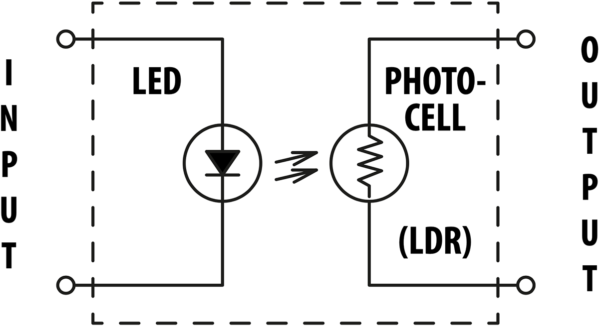
Vactrols are a common kind of optical isolator often used in circuitry that requires different circuits to be electronically isolated from each other but still able to interact. A vactrol consists of a combination of a light dependent resistor (LDR) and a light source (often a LED, light emitting diode) both integrated in a small light-proof case.

The vactrol works by a very simple principle: When input current is applied to the LED element the output LDR turns on and, as the only connection in between the two is light, the output produced is largely dependent on the LDR response. An increase in the LED brightness will cause a decrease in the LDR resistance. This effect can be used in circuits that require variable resistors to obtain the desired function (for example VCFs, VCAs, VC phasers, VC trigger delays, VC slew limiters, VC Envelope Generators, VC LFOs, VCOs and many more).
However, mechanical and electrical tolerances will cause each vactrol to behave a bit different from another (for example due to differences in alignment and distance between LED and LDR). This is why identical circuits featuring vactrols will behave or sound a little bit different from each other. Also, another aspect of the vactrol response is the LDR element; that will not respond immediately to the illumination change induced by the LED but will have a certain “sluggishness” built in. The LDR response curve is largely logarithmic and thus it may take a few seconds until the LDR reaches its "dark resistance" (the maximum resistance without illumination). In the upper brightness range it will also respond much faster: up to 50 Hz and more, which corresponds to a response time in the 10 ms range. The essentials of vactrols' behavior will depend very much upon the LDR type and the light-sensitive material used.
As a consequence of the things described above, vactrol based compressor circuits (often called opto compressors) have historically often been considered particularly natural sounding; while a modern VCA compressor can respond almost theoretically perfect with a constant ratio and predictable attack/release curves, many older optical designs have strange attack and release characteristics. In optical compressors, this is originally due to the relatively slow response of a vactrol compared with a transistor-VCA based circuit. This is perhaps the reason why the traditional opto compressors have so much perceived character and “warmth”.
The Doepfer LPG response in Modular, coupled with a VCA or another LPG in VCA mode, can yield some really nice sounding results which can be heard among the presets for Modular FX.

Oscar Öberg – Modeling, project management
Kristofer Ulfves – Presets, validation, user manual
Henrik Andersson Vogel – Marketing
Niklas Odelholm – Graphics, validation