User Manual
Modular
Intro
Quickstart Guide
User Interface
Overview
Modular FX
MIDI Mapping
A Basic Modular Synth Patch
Basic Sequencer Patch
Beat Sequencer Patch
Linking Multiple Sequencers Patch
Basic Polyphonic Synthesizer Patch.
Performance Modules
The Preset Library
Setup Window
About CV and Gate Standards
Modules In Detail
Doepfer
Doepfer A-110 VCO (Voltage Controlled Oscillator)
Doepfer A-108 VCF8 (Voltage Controlled Filter)
Doepfer A-132-3 Dual Linear/Exponential VCA
Doepfer A140 ADSR Envelope Generator
Doepfer A-147 Voltage Controlled LFO
Doepfer A-118 Noise + Random Voltage
Doepfer A-114 Ring Modulator
ROLI Seaboard RISE Module
In Use
DAW and MIDI Interfacing
DAW Sync
MIDI to CV
Quadraphonic MIDI to CV
MIDI to Trigger
Effect
Delay
Mixer Modules
The Sequencer Modules
Beat Sequencer
Sequencer 16, Sequencer 8 and Penta Sequenza
The Utility Modules
Sine Oscillator
Envelope Follower
Multiple
Offset
Quad Offset
Sample and Hold
Slew Limiter
Divider
Logic Tool
Signal Tool
Switch 1 to 4
Switch 4 to 1
Dual Pan
Dual X-Fade
Utility Quantizer
MIDI Step Sequencer
Credits
Before there were Minimoogs, Odysseys or any of the Japanese compact performance synthesizers, there was the modular synthesizer. The modular synthesizer consisted of the core building blocks—modules—for sound sculpting; tone generators (also known as oscillators), fixed filters and modifiers. These were separate units which could be interconnected, usually using patch cords. The fact that the individual modules could be patched in a number of configurations opened to a wide range of sonic options.
Doepfer And The Eurorack Synth
In the mid 1990s, there was a modular synth revival when German synth designer Dieter Doepfer launched his range of modular synthesizers. Doepfer’s system was called A-100, and the modules were housed in Eurorack casings, a rack format previously used extensively in the telecommunications industry. Soon, a large number of synth vendors started coming out with their own modules for the Eurorack standard. Today, there are over 4000 Eurorack modules available from over 150 different vendors.
Softube Modular
Softube Modular is a virtual Eurorack modular synthesizer, which is used as a plug-in in any major DAW. Modular was developed in close collaboration with Dieter Doepfer, and six Doepfer modules are included in the basic Modular package, along with more than 20 of Softube’s own utility modules. More modules can be purchased separately to expand the options from the basic package.
Modular can be used just like an actual Eurorack modular synth, by adding different modules and combining them using virtual patch cords. A Eurorack modular synth is by definition monophonic and so is also the Softube Modular, although a certain degree of polyphony can be achieved. More of this later. The analog synth modules have been modeled, component by component, by Softube’s engineering team. Therefore, Modular is sonically impossible to distinguish from its analog counterparts. Furthermore, just like a real life Eurorack synth, any audio signal can be fed into the modules. To facilitate using Modular this way, we have created a separate plug-in called Modular FX.
It goes without saying that the experience of connecting actual patch cords and tweaking physical synth modules can never be replicated in the software domain. But the fact that Modular resides in the computer opens to a few possibilities that are not available with physical Eurorack synthesizers. First of all, patches (complete setups of modules, their interconnections and settings) can be easily saved, instantly recalled and shared with other Modular users. Second, a large number of professionally made presets are available. That makes Modular instantly usable also to inexperienced users—and offers a great way to learn more about modular synths. Furthermore, Modular offers PERFORMANCE MODULES, which makes it easier to highlight and adjust a select number of parameters on the fly, even with complicated patches. This makes Modular ideal to use for live performances or for inspiring music production in the studio. Plus—if you have access to physical synth modules, you can actually interconnect these with Softube Modular via an audio interface.
If you’re familiar with working with software (and hardware) synthesizers, this section may be all you need to get started. Refer to the in-depth sections of this manual to learn the details.
When launching Modular, you will find that its default state is an empty patch, and as no modules have been added to the rack yet, you find yourself presented a choice of modules in the MODULE SELECT VIEW view. By selecting modules you can start to create your patch. You can also open a preset patch from the extensive factory library in your DAW. This is slightly different depending on which DAW and plug-in format you’re using (please refer to your DAW’s User Manual). If you open a preset patch, you will note that the patch cords appear when you move the mouse pointer over them, and otherwise fade away.
To add multiple modules without exiting the Module Select view, press Shift while clicking to select.
To connect two modules, click and hold a jack. To facilitate patching, the inputs to which the patch cord can be connected will be marked with a color, green (INPUTS) and red (OUTPUTS). An output can only be connected to an input and vice versa. Simply drag and drop the cord on the desired jack. Multiple patch cords can be routed from an output (red) to several destination inputs (green), but an input jack can only accept one patch cord at the time. If you add more modules than fits your screen, you can scroll to see them all by clicking and dragging anywhere, except over a knob or jack. Scrolling can also be performed by smart gestures or scroll wheel if your computer supports this. Any patch can contain up to 100 modules, depending on the size of the modules. Just like a physical Eurorack synth, to hear your creation, you will need to finish your patch by connecting it to Modular’s outputs. These are located in the CENTER ROW. Similarly, in order for your patch to be controllable via MIDI, you need to add the MIDI to CV module to interface with your DAW. Getting MIDI clocks from your DAW is achieved through the DAW Sync module.
These are the main sections and features of Modular.
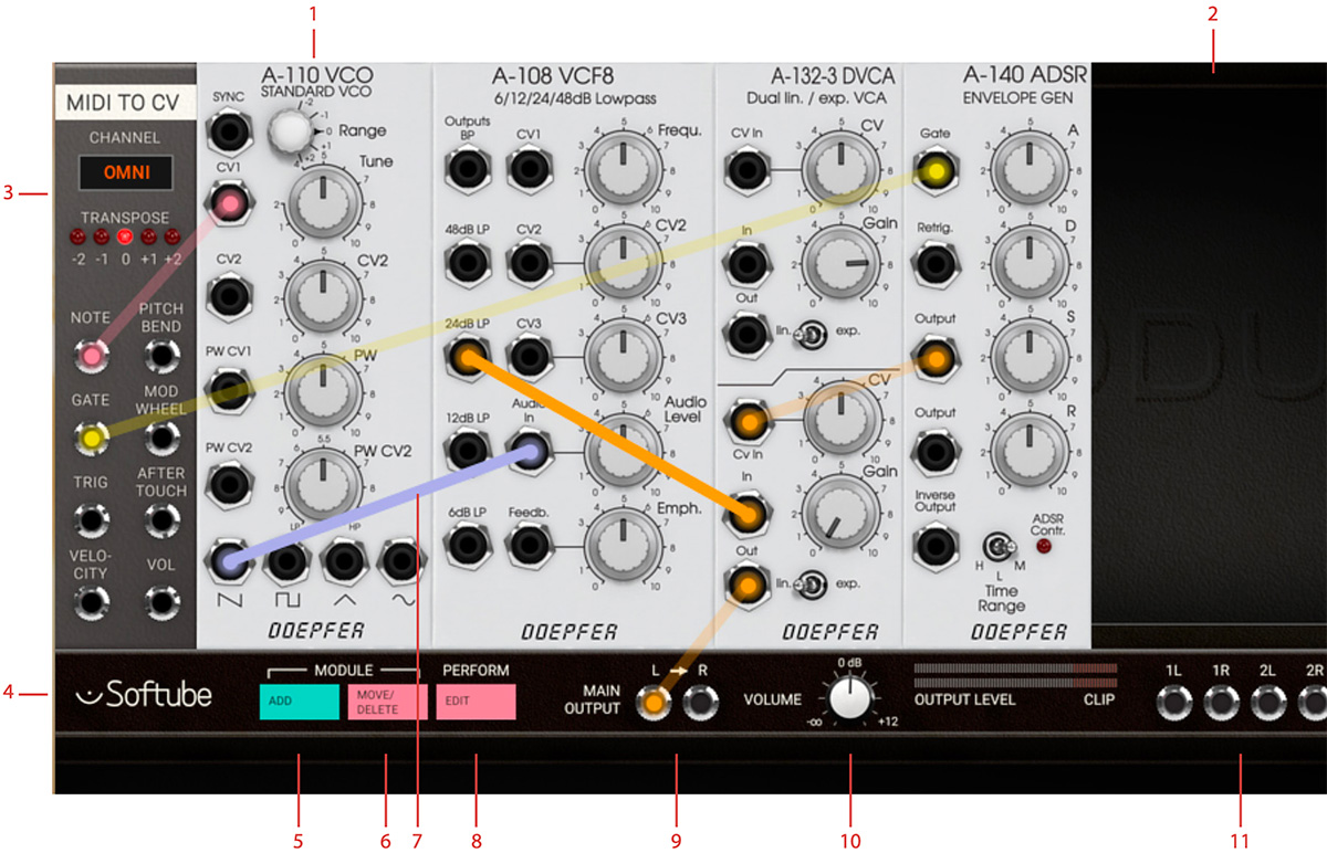
Click here to view the full-sized image in a new tab
- This is a Softube emulation of a Doepfer A-110 Oscillator module.
- This is the empty rack space where new modules are placed.
- To make Modular respond to incoming MIDI signals from your DAW or a MIDI controller, you need a MIDI To CV module in your patch.
- Center Row. Here, you have access to Modular´s main functions, as well as inputs and outputs.
- Click to enter Module Select View, where you select which modules to use in your patch.
- Enter and exit Move and Delete mode.
- This patch cord connects one of the oscillator´s outputs to the input of the Doepfer Filter module.
- Enter Performance knobs linking mode.
- Main Output. Both these need to be connected to achieve a stereo image to your DAW. Left output is normalized to the right, so connecting only L will result in a mono signal output on both channels.
- Output volume and meter.
- Aux Outputs.
The Softube Modular plugin consists of an empty Eurorack that can be filled with Eurorack modules, your building blocks, for building your patch. The CENTER ROW is situated between the first and second row of your rack area. The Center row consists of the buttons for adding modules, moving around or deleting them, as well as the button for editing your Performance modules.
Also situated on the CENTER ROW is the INPUT (only on Modular FX) and output jacks for audio. Here’s also the main Output Volume knob and its Output Level meter which indicates if the signal is clipping. The Modular Eurorack workspace can be scrolled up and down by clicking and dragging on the background or on the module panels in the patch view. Using the scroll wheel on your mouse or smart gestures (two finger scrolling) is also supported.
When scrolling, the CENTER ROW will scroll along, but stay at the top of the screen. Controls within modules (knobs, slider, switches) can be moved by clicking and dragging the mouse cursor over the parameter. A parameter can be reset to its pre-set value by clicking while holding Alt key. Fine adjustments can be done by holding ⌘ (Mac) or CTRL (Win), while clicking and dragging on a parameter.
Handling Modules
The modules are the building blocks from which you create your modular synth patch, just like in a real life Eurorack modular. When you launch Modular, you will see the two top rows of rack space (empty by default), divided by the horizontal CENTER ROW. The rack space is where the modules will go as you add them. You can scroll down to see additional empty rows of rack space.
On the far left side of the CENTER ROW, two buttons are labeled Module, one to Add and the other to Move/ Delete. Clicking Add opens the MODULE SELECT VIEW. Here, you will see all your available modules, sorted by brand and type. Placing your mouse pointer over a module opens a brief description. The details of each module is covered in "Modules In Detail". Clicking a module adds it to the rack. You can hold SHIFT and click to add several modules at once to the rack. Exit MODULE SELECT VIEW window by clicking the pink “X” icon in the upper right corner.
Move/Delete View
Having added modules to your rack, you can click the Move/Delete button in the CENTER ROW to move or delete them. While in MOVE/DELETE VIEW, the Move/ Delete button is lit and the added modules are darkened with an added “X” mark in each upper right corner. Clicking on this “X” will delete the module.
By clicking at a module, it becomes highlighted, indicating that it is now selected for moving. Click on an empty space in the rack to where you want to move the selected module or move the module by clicking and dragging the module to the desired location. While being moved, the module will turn opaque when you drop it to a new location. If you drop it while it's semi-transparent it will be positioned back to its previous position.
Exit MOVE/DELETE VIEW by clicking on Move/ Delete button again. The button is unlit as you’re back in normal PATCH VIEW.
Patching
When you have added modules to the rack, you need to manually connect them using patch cords. To add a connection, click and hold an output jack on a module. A circle appears, and if you move the mouse (still holding the mouse button down), a patch cord is drawn from the output.
Any input jacks that can be used as a destination for your current connection will turn green. If you are instead patching from an input, all the available destinations will of course be outputs, marked red. Drag the patch cord to one of these and let go—the connection has been made. When you move away the mouse pointer, you will see the patch cord fades away. The two connected jacks will be marked with the same color as the patch cord, and if you move the mouse pointer back near any of the patched jacks, the cord will reappear.
To alter a connection, click on a jack and move the cord to another jack. Since multiple connections can be patched from the same output jack, patchcords can only be removed from the “input-jack side”. To remove a connection, drag the cord on the input jack side to somewhere where there is no other jack and let go. Multiple cables can be stacked from the same output but only one can connect to the same input. This can be useful for example when using a single envelope generator output to control multiple other modules.
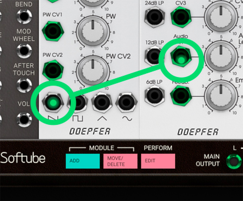
Patch from an output jack, and all inputs will get highlighted with a green color.
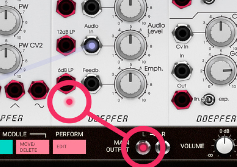
While patching from an input, all outputs will get highlighted with a red color.
The Output Section
Any patch must end with a connection to the Main Output jacks on the CENTER ROW, otherwise, no sound will come out of Modular. The LEFT output is normalled to the RIGHT, which means that if your patch is only connected to the LEFT output, the sound will be in mono. To create a stereo patch, both LEFT and RIGHT outputs must be used. The Volume knob lets you adjust the output volume to reasonable levels, as indicated by the Output Level meter. Avoid running this into the red segments, labeled CLIP.
The CENTER ROW also has four stereo pairs of auxiliary outputs, labeled Aux Outputs. These can be used to send separate outputs to your DAW.
This can be useful for further processing in your DAW, or to route signals from Modular to a hardware Eurorack system.
The Block DC On Aux Out buttons is a feature used to make the Aux outputs sending ordinary AC (audio voltage) in order to interface with your hardware Eurorack system. However, setting the Block DC to OFF should be used with utter care. A large DC offset directly to your speakers can damage your hearing and/or speakers.
Understanding Control Voltage
A physical Eurorack modular synth communicates via CV (control voltage), which Modular emulates. CV is used to control parameters such as pitch, cutoff frequency, pulse width and more. An interesting aspect of Eurorack modular synths is that there is no real difference between audio and controller (CV) signals. These can be mixed or used to interact with each other, for example using the output of an oscillator to modulate the cutoff frequency of a filter, so called “Filter FM”.
Events in a Modular synthesizer are often triggered by a GATE or TRIGGER pulse. A GATE signal is a pulse that is extended high until released, typically the output of a MIDI to CV module where the GATE signal corresponds to MIDI note on (GATE rising edge) and MIDI note off (GATE falling edge) messages.
Certain modules requires a short pulse, rather than a GATE. This is called a TRIGGER pulse. Examples of modules that work best with TRIGGER pulses are for example the Heartbeat drum modules (using the MIDI TO TRIGGER module or BEAT SEQUENCER) and SEQUENCER modules.
Interfacing With DAWs And MIDI Controllers
The fact that Modular uses CV also means that it interfaces to DAWs and MIDI controllers in a less integrated—but much more flexible—manner compared to most software instruments. Any connection between Modular and a DAW or MIDI controller requires at least one of the modules in the DAW and MIDI INTERFACING category in MODULE SELECT VIEW.
In order to use MIDI signals from a DAW or a physical MIDI controller to play notes or control parameters, you need to add one of the MIDI to CV conversion modules to your patch. These modules convert the incoming MIDI data to virtual voltage, which the Modular’s modules can react to. You will then need to patch the outputs of these modules to the modules you would like to be affected by the DAW or MIDI controller.
Similarly, to make any of Modular’s modules synchronize to the DAW tempo, you need to add the DAW Sync module, and patch that to the sequencer or LFO module you would like to have synchronized. See the detailed description of the DAW AND MIDI INTERFACING modules in the "Modules In Detail" and go through the "A Basic Modular Synth Patch" to see an example of this in use.
Performance Modules
Both in the studio and during a live performance, a big part of the attraction to using synthesizers is the ability to alter sounds on the fly by adjusting parameters as the music plays. But even with complex patches using a large number of modules, there is usually a limited number of parameters you are interested in tweaking as you go. These parameters can, however, be spread out across a number of different modules that may be placed far from each other in the rack, making live adjustments impractical. To facilitate sound tweaking on the fly, we have included the user definable PERFORMANCE modules. These have controls (knobs, switches and/or sliders) that you can freely assign to any parameter within your patch. This lets you gather the parameters you would like to play with in a single spot. The parameters become easy to find and easy to assign to a physical MIDI controller.
For more info, please see "Performance Modules".
Sequencing
Four different sequencer modules are included in the Modular basic package. You will find them under the SEQUENCER category in MODULE SELECT VIEW. These can be used for analog style step sequencing, and can be synced to your DAW tempo using the DAW SYNC module.
For more info, see "The Sequencer Modules".
The Softube Modular can also be used as an audio effect. So instead of basing a patch on an oscillator, you can base it on any audio signal–a guitar, a drum loop or a vocal recording. The only difference is that, as an audio effect, the CENTER ROW will also contain an INPUT stereo pair. This is where the audio enters the Modular FX. Patch and process your incoming audio through any of the Softube Modular effects in order to build your own effects, or just load some of the included Modular FX presets.
CV: Control Voltage. A signal that controls other modules.
VCO: Voltage Controlled Oscillator. A module that generates waveforms (makes sound).
VCF: Voltage Controlled Filter. The basic approach to synthesizers is to use a harmonically rich audio signal, such as a sawtooth waveform, and use a filter (VCF) to remove "unnecessary" harmonics. This is called subtractive synthesis.
ADSR: Attack/Decay/Sustain/Release. Converts on/off information to a nice envelope with variable attack, decay, sustain and release.
VCA: Voltage Controlled Amplifier. This is a CV controlled volume knob, usually used to apply an ADSR envelope to control the volume of a signal.
LFO/VCLFO: Low Frequency Oscillator, usually Voltage Controlled. Basically the same as a VCO, but for very low frequencies. Use to create vibratos, pulse-width modulations, etc.
Softube Modular can be mapped to any midi-controller that can output MIDI controller change (sometimes just called MIDI CC) data. This can be done through the MIDI CC linking mode menu at the top right in the plugin.
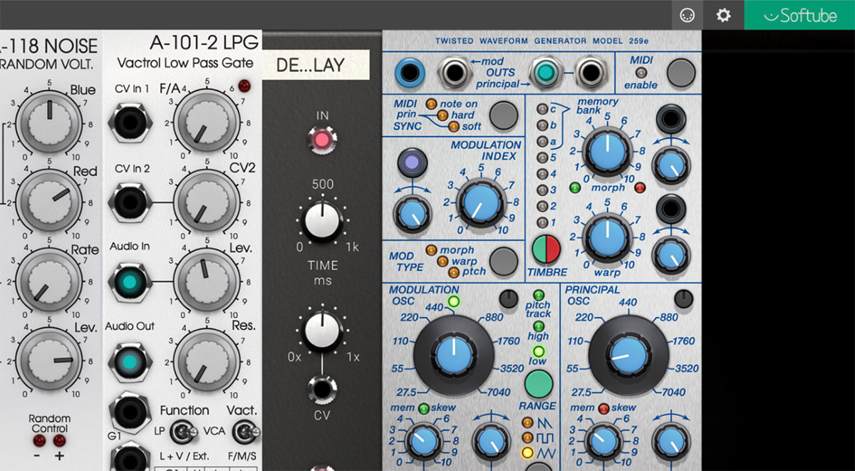
When clicking on the MIDI symbol, this dropdown menu appears displaying all previously mapped parameters in your project/song (if any) and at the top the option for you to enter MIDI CC linking mode by clicking on the text that says “Click here to enter MIDI CC linking mode”. At the bottom, the “Load from file...” and “Save to file...” options – more about these later.
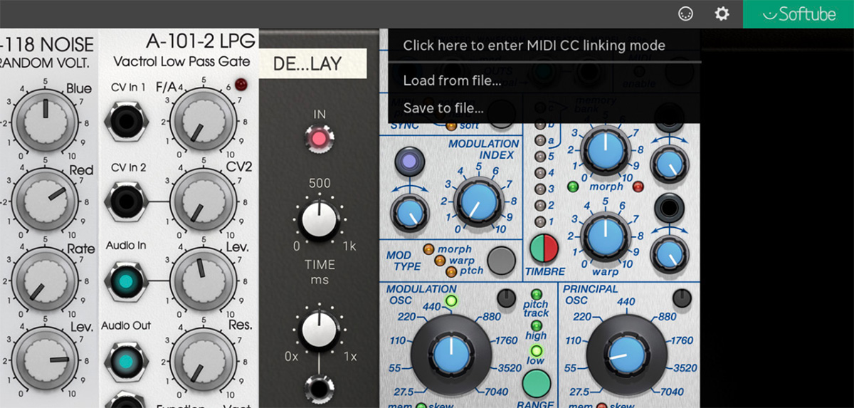
After entering MIDI CC linking mode by clicking on the text “Click here to enter MIDI CC linking mode”, the on-screen message will prompt you to “select parameter to link with MIDI CC” and this means that you can click on any parameter you would like to link to your controller.
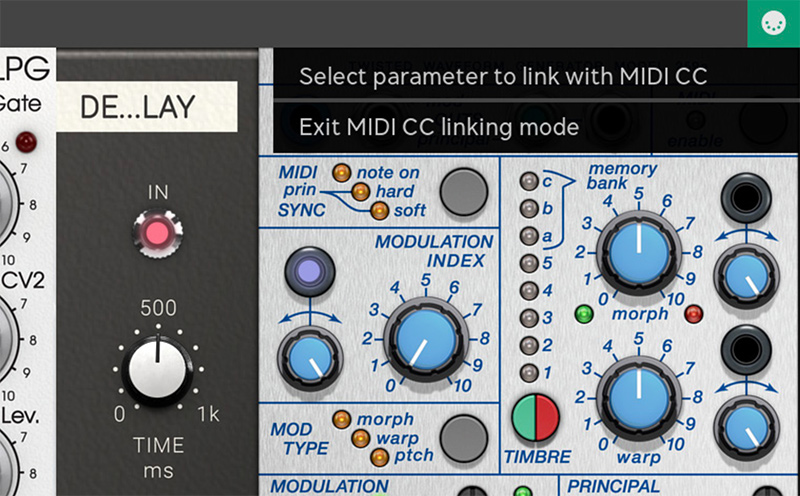
After clicking on a parameter of choice you'll be prompted to move the slider or dial on your midicontroller to link this physical controller to the chosen parameter in Modular. If there were a mistake you can always click on “Exit MIDI CC linking mode” to abort this operation.
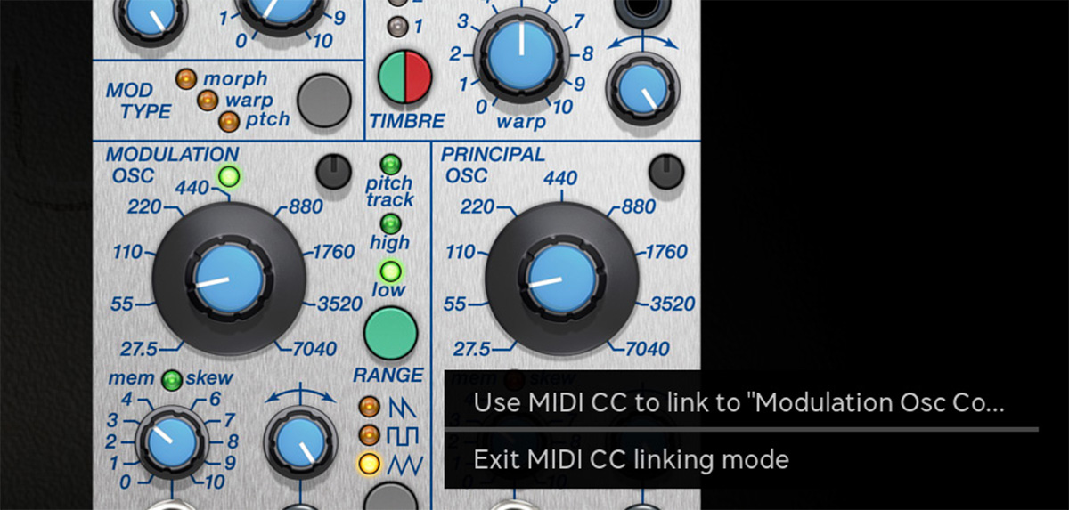
Now you have tweaked your MIDI controller and will see the knob you linked it to moving on screen while you're moving it – like magic! An on-screen message displays the parameter name link and to which MIDI CC message it is linked to. OK, something went wrong? Don't worry – you can unlink the controller again just as easily by clicking on the unlink ”parameter name”- message.
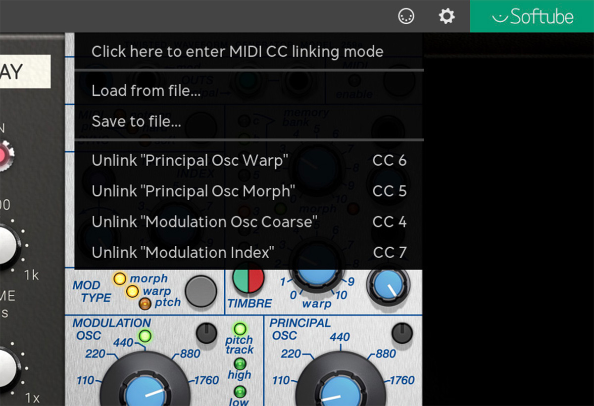
Any number of parameters can be linked to the same MIDI controller knob although multiple knob cannot be linked to the same parameter.
Exit MIDI CC linking mode by clicking on “exiting MIDI CC linking mode” in the on-screen pop-up or by clicking on the MIDI symbol in the top left corner again. All linked parameters will be listed in the dropdown menu until you click elsewhere in the GUI.
The “Load from file...” and “Save to file...” options in the top menu are used for saving and loading previously mapped MIDI controller templates in the file format “.softubemidipreset”. A word of caution - since the Modular parameter set is dynamic this functionality can be confusing when loading a previously saved map within a “.softubemidipreset”-file on to a preset structure that it was not intended to control.
The saved midi map contains information about the instrument-type (Modular in this case) and will not be able to load within another Softube instrument (for example Model 72).
Click here to view the full-sized image in a new tab
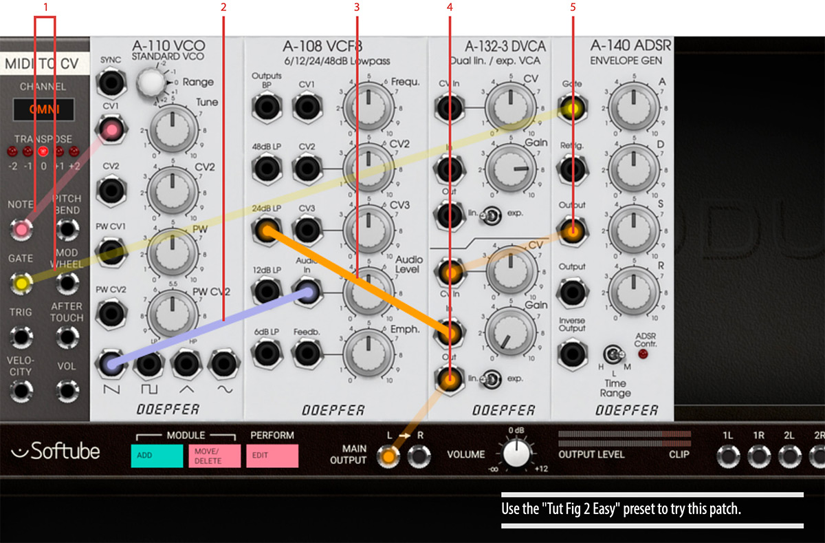
This is the smallest patch that uses all of the classic synth parts.
- The MIDI TO CV sends note information to the tone generating oscillator (VCO), and on/off (Gate) information to the envelope generator (ADSR).
- The sawtooth output from the VCO is sent to the low pass filter (VCF).
- The low pass filtered signal is sent to the amplifier (VCA) where its volume will be controlled by the ADSR via the CV In.
- The ADSR converts the on/off information into an envelope with variable Attack, Decay, Sustain and Release, which is used to control the amplifier (VCA).
- On the VCA, turn down Gain so it is 100% controlled by the CV signal. Finally, the output from the VCA is sent to the Main Output.
When sending a MIDI note from your DAW (for example by pressing a key on your MIDI controller keyboard) a note with a slow onset will be heard.
Raise the cutoff frequency (Frequ.) on the VCF module fully clockwise to brighten the tone. This can be automated and controlled by the ADSR envelope—connect one of the outputs of the ADSR to the CV2 jack of the VCF, lower the cutoff frequency again and a familiar filter sweep will be heard each time you strike a note.
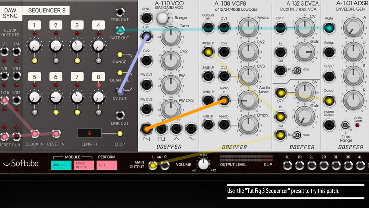
This is another simple example on how to set up a eight step sequencer to be synced by the DAW to control the simple patch build above. The DAW SYNC module outputs a clock, in this case 16th notes, that is patched into the Clock In of the SEQUENCER 8 module.
In order to get the sequencer to start from the beginning when the DAW playback is restarted, the Reset pulse jack of the DAW SYNC module is connected to the Reset In jack of the SEQUENCER 8. Now, when the DAW is started, the Sequencer will slave to its tempo and output CV, gate and trig information. By connecting the CV out to the CV1 in on the DOEPFER A-110 VCO module, the SEQUENCER 8 steps can control the pitch of the oscillator. When controlling the pitch of an oscillator it is recommended to engage the Quantize button on the sequencer module, since this will quantize the outgoing voltage to a chromatic scale. Gate Out or Trig Out can be used to trigger an envelope generator, such as the A-140 ADSR, used in the example above. The difference between the Gate Out and the Trig Out is that the Gate Out’s pulse lengths are longer and that several programmed gates after each other, creates a legato note on the Gate Out. In the example above you can see and hear this on step 6 in the sequencer.
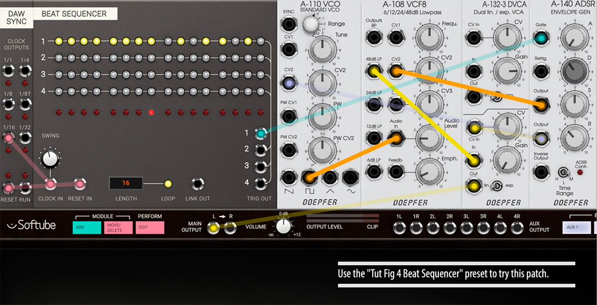
Using the BEAT SEQUENCER with the DAW SYNC module is more or less the same procedure as the previous example, but with the big difference that this sequencer module doesn’t send out any pitch information, only triggers. Another difference is that the BEAT SEQUENCER has four tracks of triggers, each with its own output. These trigger outputs can be used to trigger any kind of event: an envelope (like the A-140 used in the example), another sequencer, a drum module, a clock divider, a sample and hold module et cetera.
In this patch the DOEPFER A-140 ADSR output is used to control not only the volume of the sound (by connecting it to the A-132-2 DVCA’s CV input), but also to control the A-108 VCF’s filter cutoff frequency (by connecting it to CV2 in), as well as to control the pitch sweep of the A-110 VCO (by connecting it to CV2 in on the A-110). This creates the synth-tom sound which is triggered from the BEAT SEQUENCER.
Linking Multiple Sequencers Patch
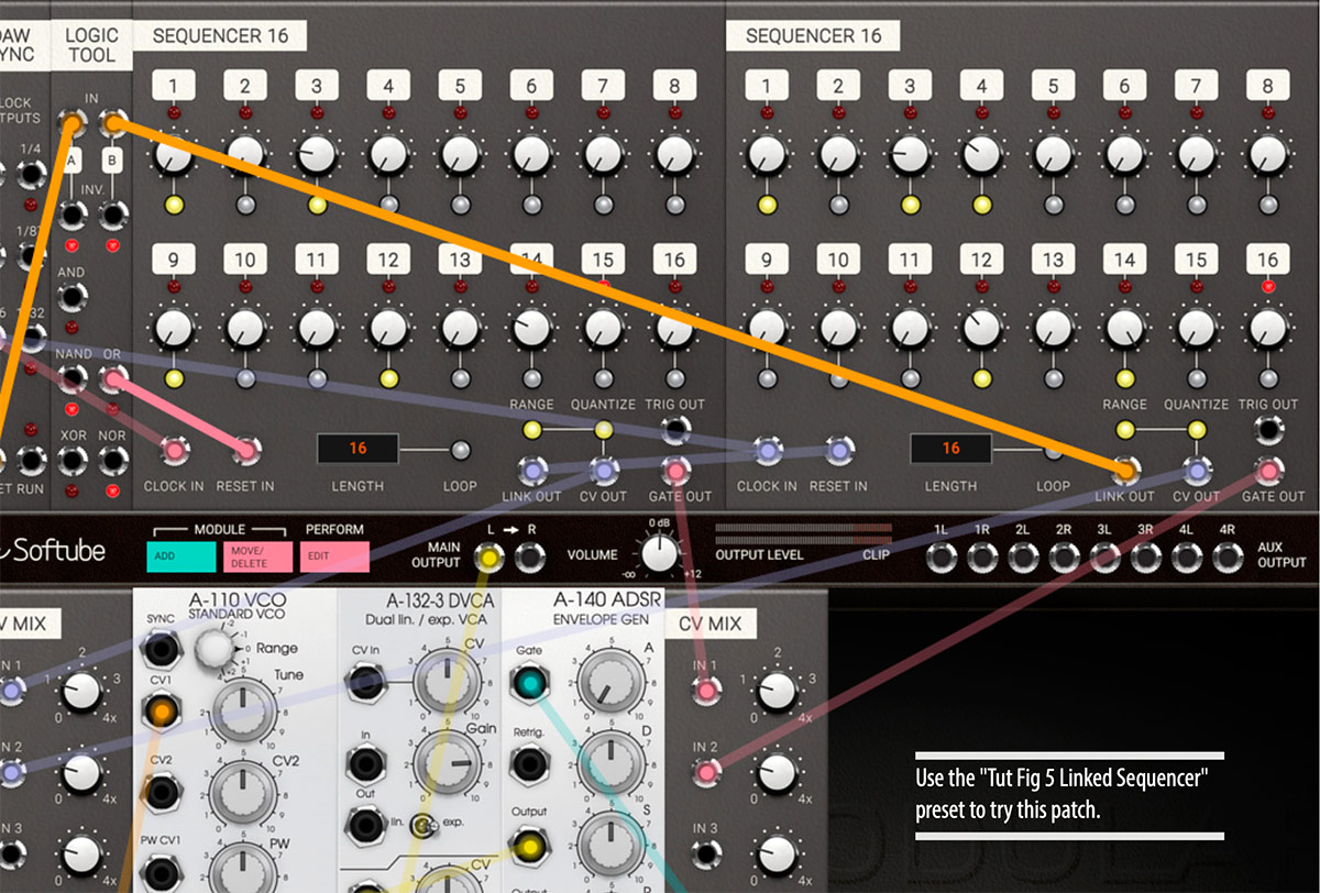
This example patch uses two linked 16 step sequencers in order to achieve a 32 step sequence. Both 16 step sequencers are clocked from the same clock source (16th notes from DAW SYNC). But they get their reset clocks from the linked out pulse which is transmitted after the last step when the sequencer is not in loop mode. The CV and gates from the two sequencers are mixed together to control the simple synth setup (VCO, VCA, ADSR) at the bottom. The logic tool is used for the logic function OR on the DAW SYNC's Reset pulse and the Link Out pulse from the second sequencer. This patch has some flaws but it is a good starting point for further patching.
Basic Polyphonic Synthesizer Patch
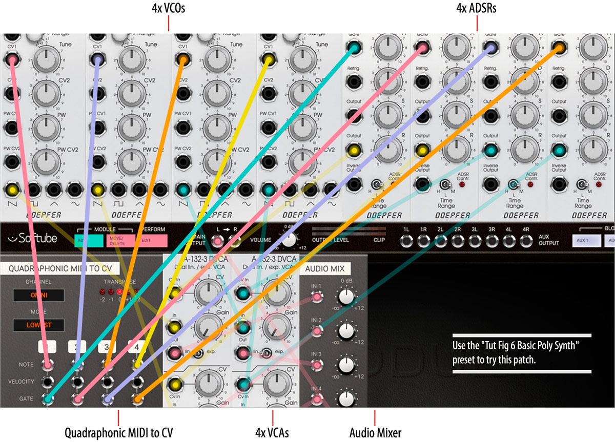
Click here to view the full-sized image in a new tab
It's possible to build four voice polyphonic patches with Softube Modular using the QUADRAPHONIC MIDI TO CV module. But just like with a world Eurorack system, this takes four times more modules if each voice needs its own oscillator, filter, etc.
This example demonstrates how a polyphonic patch is set up. Each voice in this really simple patch consists of a VCO going into a VCA that is controlled by an ADSR envelope. Each voice gets its own note CV from the QUADRAPHONIC MIDI TO CV module and in the same manner, each voice also get its own gate information sent to its dedicated ADSR envelope. The ADSR output is connected to the CV In on the VCA controlling the overall volume of that voice. The VCA of each coive is then summed in the Audio Mixer before being sent to Main Output. Experiment with the QUADRAPHONIC MIDI TO CV voice modes to see the difference between rotating assign and lowest assign modes.
The PERFORMANCE MODULES offer a nice way of getting easy access to a selection of parameters from all modules in your patch in one convenient location. The modules can be used to create what could be called a macro-area containing all the parameters you want easy accessible for your performance. A Performance knob, switch or slider can be linked to any parameter within your patch, making it possible for you to create a custom interface to your patch.
Performance Linking In Detail
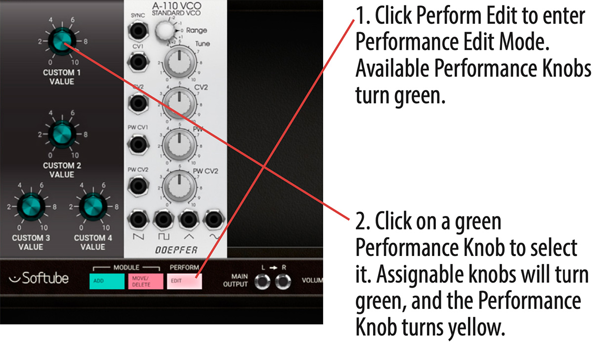
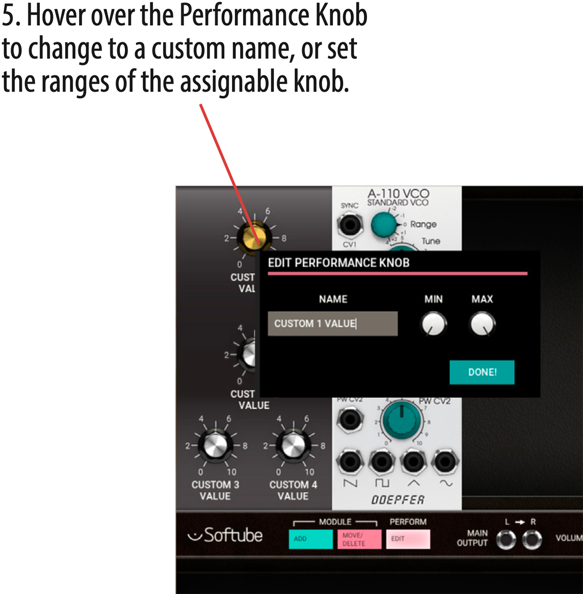
The knobs, switches and sliders on the PERFORMANCE MODULES can be edited to control parameters within your patch, all from one convenient place. Click on the Perform Edit button on the CENTER ROW to enter PERFORMANCE EDIT MODE, which is indicated by the activated Perform Edit button. Patching is disabled in PERFORMANCE EDIT MODE.
In PERFORMANCE EDIT MODE the knobs on the PERFORMANCE MODULES in your patch that are unassigned will become green tinted, and the text label underneath will also say “CUSTOM VALUE”.
By clicking on one the green performance knobs, the knob color turns yellow indicating that you have selected this particular knob for being assigned to a parameter within your patch.
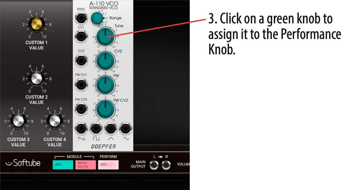
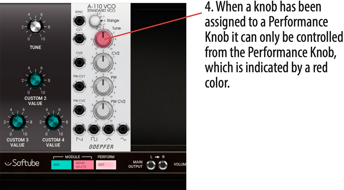
All controls in your patch that are available as destinations, will now be indicated by turning green. Click on the control (knob, switch, slider) within your patch you want as your linked destination. This knob will turn transparent red to indicate that it is linked to a performance knob. The slaved parameter will get disabled as long as it is slaved to a performance module.
The Performance knob name can be edited by hovering your mouse pointer over it until a window appears. In this window, you can write your custom name for the knob’s function and also set custom ranges using the Min and Max knobs.
To unlink a performance knob, double click it and the parameter slaved to it will lose its red color and be available for normal use again.
To exit PERFORMANCE EDIT MODE, click the Perform Edit button again and its appearance is reverted back to normal as you're back in PATCH VIEW.
LEDs on Performance modules
LED indicators on PERFORMANCE MODULES and its corresponding input jack is for visual reference and can be used for displaying an audio level, gate indication or clock rate. Blinkenlights!
Modular comes with more than 200 preset patches. Use your DAW’s preset browser to browse through the patches. They are organized as follows:
Bass: Different kinds of bass synth sounds.
Brass: Trumpets, horns (OK, we also included some flutes here).
EFX: Effect sounds.
Lead: Different kinds of lead synth sounds.
Pads: Mono and poly chord sounds.
Perc: Different kinds of percussion sounds.
Sequenced: Sequenced and pseudo-sequenced sounds.
Strings: Lush and analog, acoustic and murky.
Tutorial patches: Good starting points, described in the tutorial examples above.
Heartbeat: Sounds that make use of the Heartbeat modules.
Expansion: Sounds that requires add-on modules, for example Intellijel modules.
Artist: Presets created by artists.
Modular FX: Presets made for the insert version of Modular, to be used with an external audio source. These are only available in Modular FX.
Clicking the Setup tab in the bottom right corner of Softube Modular’s graphical user interface will bring up the setup configuration menu. Some of the changes made here will only take effect after relaunching your DAW.
Always use smaller GUI: This forces the GUI to remain small even if higher resolution is supported by your computer screen. Uncheck this if you want to use a larger GUI.
Use medium GUI on large screens: This forces the GUI to remain medium sized even if higher resolution is supported by your computer screen. Also uncheck this box if you want to use the largest GUI.
Show value display: Toggles the value display in the lower left corner of Softube Modular on and off.
The mid 1960s was an exciting time with huge leaps forward in technology for synthesizing sound. It has since then been widely debated who really invented the voltage control for synthesizers. Nevertheless, voltage control was a significant invention that enabled all synthesizer modules to communicate to each other and it was Bob Moog that standardized CV. 1 Volt/Octave for pitch was the first standard to prevail although many other manufacturers for a long time also used other standards such as Hz/Volt (which respond to each octave by a doubling of voltage).
For triggering of electronic switches and envelope generators within his system, Bob Moog used the so called s-trig (short trig) standard where others used the V-trig (voltage trig) standard. The latter eventually became more popular and is today the standard when we talk about CV (control voltage for pitch) and Gate (for triggering sequences, envelopes etc).
The Eurorack standard, more or less set by Dieter Doepfer with his A100 system, use the linear CV and V-trig standard. There are three types of signals within a Eurorack system:
Audio Signals: Ranges from -5 to +5v
Control Voltages: Typically range within 0 to +8v, as for example the output of an ADSR
Trigger Voltages: Range 0 to 5v, trigger occurring at leading edge
All these three signals can be patched without restrictions within the system, which means that audio can be used to trigger logic modules designed for use with trigger voltages or as modulators connected to inputs designed for control voltage. The system will not differentiate between the types which makes the Eurorack system extra intuitive, open for experiments and happy accidents.
In this section each module of the Softube Modular is described in detail, with added suggestions on use. In Description Legend below we define how each module is described and what the different sections described refers to.
Description Legend
Names in bold
Refers to knobs, switches, dials, input/output jacks, etc.
NAMES IN CAPS
Refers to a parameter setting, or the name of a module or function.
[descriptive text]
Text within brackets is a description of a symbol on the panel, for example that of an waveform or other graphical element.
Parameters
Refers to knobs, dials, switches on module and are described from left to right, from top to bottom on module.
Inputs
Refers to the input jacks of the module used for input of audio or CV. They are described from left to right, from top to bottom on the module.
Outputs
Refers to the output jack of the module used for outputting audio or CV. They are described from left to right, from top to bottom on the module.
In Use
Detailed description of the module’s functions as well as some tips and tricks.
This category contains the modules from legendary Eurorack manufacturer Doepfer. These include a VCO, VCF, VCA, ADSR Envelope, LFO and a Noise source—all you need for building your own basic subtractive synthesizer patch.
Doepfer A-110 VCO (Voltage Controlled Oscillator)
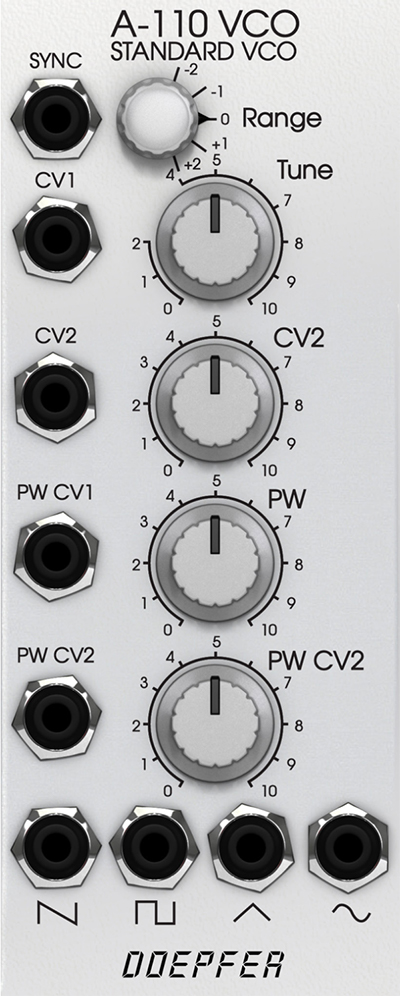
An oscillator is a tone generator, the most basic building block of a synthesizer. The Doepfer A-110 can generate four different waveforms, each with its distinctive own overtone spectrum.
Parameters
Range: Octave offset ranging five octaves
Tune: Fine tune up and down one whole note, preset setting 5 is tuned to 440 Hz when playing an A3 from a MIDI keyboard.
CV2: Sets the amount of CV modulation of the incoming signal at CV2. Knob turned fully clockwise is full 1v/octave range.
PW: This knob sets duty cycle of the pulse wave. The preset setting 5 is 50%, also known as a square wave.
PW CV2: This knob controls the amount of pulse width modulation by incoming CV at PW CV2 jack.
Inputs
SYNC: Incoming signal on this jack resets the oscillator, often referred to as hard sync on other synthesizers.
CV1: CV control of pitch, full range 1v/ octave. Connect your note CV from MIDI to CV converter module to this jack.
CV2: CV modulation input, connected with CV2 knob (see above).
PW CV1: CV control of pulse width, full range.
PW CV2: CV control of pulse width, connected with PW CV2 knob (see above).
Outputs
[saw]: This jack outputs a saw wave, a harsh and clear sound containing both even and odd harmonics.
[pulse]: This jack outputs a variable pulse wave, a more hollow sound than the saw wave which contains mostly odd harmonics when the pulse width is 50% (PW knob set to 5).
[triangle]: This jack outputs a triangle wave, also a very hollow sound suitable for synthesizing flutes, vibes and organ sounds.
[sine]: This jack outputs a sine wave which is a waveform that only contains the fundamental, none of the overtones. This is thus not suitable for subtractive synthesis (shaping the sound with a filter).
In Use
Connect the Note CV out from your MIDI TO CV converter to CV1 on the A110 for accurate full tracking of the A110. By connecting Note CV into the CV2 and using the CV2 knob, microtonal changes smaller than 1 V/Octave tracking can be obtained. Connect Sync jack to the square output of another oscillator to achieve hard sync. This means that A110 is reset by the other oscillator which can be heard when raising the pitch of the A110 above the other one’s—the harmonic spectrum of the outputted signal of the A110 is now changed. Control the A110 pitch by envelope, LFO or similar to achieve moving “hard sync sweeps”.
The Softube Modular Doepfer A110 module models the real hardware with all its flaws and quirks. This means, for instance, that the triangle and sine outputs are not “mathematically clean” but has the additional harmonics just like the original circuits they are modeled upon. This gives the module character and a nice musicality, but if you prefer a “clean” sine waveform we advise you to use the UTILITY SINE OSCILLATOR instead.
Doepfer A-108 VCF8 (Voltage Controlled Filter)
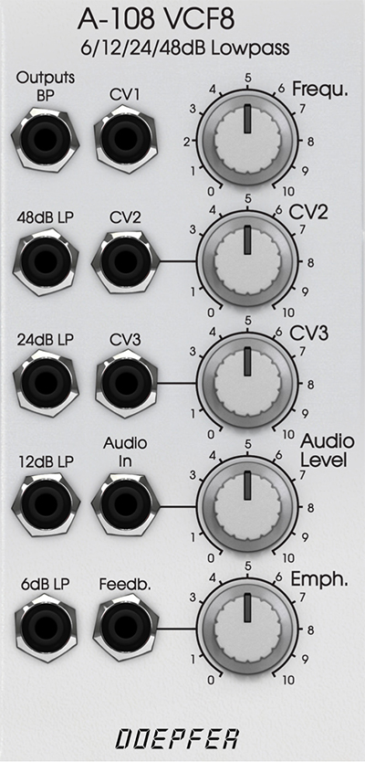
Voltage Controlled Filter based on the well-known transistor ladder filter (the “Moog” ladder) but with a unique external feedback path.
Parameters
Frequ: Cut off frequency of the filter.
CV2: CV2 amount, scales the incoming signal on the CV2 jack.
CV3: CV3 amount, scales the incoming signal on the CV3 jack.
Audio Level: Incoming volume of the Audio input jack.
Emph: Emphasis, this controls the feedback amount of the filter. Often also called resonance or Q.
Inputs
CV1: CV control of cutoff frequency, full range 1v/octave. Connect your note CV from MIDI TO CV converter module to this jack if you want your filter to fully track your keyboard.
CV2: CV control of cutoff frequency. This jack is tied to the CV2 knob that scales the amount of the signal from this input.
CV3: CV control of cutoff frequency. This jack is tied to the CV3 knob that scales the amount of the signal from this input.
You can have several CVs controlling the cutoff frequency, the different CV inputs are added together within the module.
Audio In: Insert the signal you want to filter here. This jack is tied to the Audio Level knob that sets the volume of the incoming signal.
Feedb: This jack breaks up the internal feedback path from the 48 dB output back via the Emphasis knob. This enables different modules to be inserted into the feedback loop. For example, inserting a VCA enables voltage controlled resonance. This also makes it possible to feed back other filter outputs than the 48dB LP to obtain a different resonance behavior.
Outputs
BP: This is the bandpass output of the filter, which means that it only passes audio centered around the set cutoff frequency. Emphasis sets the width of the pass band.
48dB LP: This is the 48dB per octave low pass filter output, the filter’s steepest rolloff.
24dB LP: This is the 24dB per octave low pass filter output, often associated with the “fat” American synthesizer sound.
12dB LP: This is the 12dB per octave low pass filter output.
6dB LP: This is the 6dB per octave low pass filter output, the filter’s least steep rolloff which gives it a very gentle impact on filtered sound.
In Use
The Doepfer A-108’s audio input is very sensitive, so distortion is possible even with normal levels. For example, distortion appears about from position 5 with the A-110 oscillator. In self-resonating mode, the filter can be used as a sine-oscillator source, tracking 1V/octave on the CV1 input jack.
Doepfer A-132-3 Dual Linear/ Exponential VCA

The A-132-3 is composed of two identical Voltage Controlled Amplifiers where each has a manual gain control and a Control Voltage input with attenuator. The character of the Control Voltage response can be set to either linear or exponential.
Parameters
CV: Control Voltage input Amount. This knob scales the incoming CV controlling the VCA.
Gain: This knob sets the Gain offset of the VCA. It can be thought of as the “minimum” level or “idle” level setup of the VCA.
Lin/Exp: This switch sets the scale response to input Control Voltage at CV in.
Inputs
CV in: An incoming signal controls the amplification of the VCA.
In: The input signal which amplitude is to be controlled.
Outputs
Out: Output of the VCA, the resulting signal.
In Use
The VCA can be used to shape and scale both audio and control signals. The most common example would be to let an ADSR envelope control the output volume of a synthesized sound in the classic subtractive configuration VCO-VCF-VCA. Other examples include letting the VCA scale the vibrato amount of an LFO to pitch where the CV input is controlled by the Modulation wheel CV from a MIDI TO CV module. The VCA can also be used to create tremolo effects when controlled from a LFO or used with the A-108 VCF8 to enable it to have Voltage Controlled feedback.
Doepfer A140 ADSR Envelope Generator

An ADSR envelope generator is a gate-triggered timecontrolled series of events outputting timed changes in voltage output. The different phases represents that of an acoustic sound described in its Attack, Decay, Sustain and Release phases.
The Attack phase is the swelling phase, from zero to the maximum value of the envelope. The Decay phase is the subsequent falling time period until the Sustain level is met. The Sustain level determines the level as long as the MIDI key (or gate voltage) is held. The Release phase is the ending time period occurring when the key (or gate voltage) is released and determines the time it takes until the envelop have reached zero again; the end point.
Parameters
A (Attack): This knob sets the Attack time of the envelope.
D (Decay): This knob sets the Decay time of the envelope.
S (Sustain): This knob sets the SUSTAIN level of the envelope.
R (Release): This knob sets the RELEASE time of the envelope.
H L M (Time Range): This 3-position switch lets you select the overall speed of the ADSR.
H: HIGH, very slow. Up to several minutes.
M: MEDIUM, standard setting.
L: LOW, very short time periods down to less than 100 μsec.
Inputs
Gate: This input triggers the ADSR envelope from a gate signal.
Retrig: This input retriggers the envelope from a trigger signal.
Outputs
Output: This is the output voltage from the envelope.
Output: This is a duplicate of the output above.
Inverse Output: This is an inverted version of the Output.
In Use
The Doepfer A-140 ADSR is a module that is triggered from a gate generated from for example a key pressing (using the MIDI TO CV module) or a sequencer. Attack and Decay sets the time of the first two stages before arriving at the set Sustain level. Release is the fall time from Sustain level when gate has been released. The ADSR envelope can be used for controlling the VCA, VCF or VCO. Also use the ADSR is to sweep the pitch of a VCO synced to another VCO for sync-sweeps.
Doepfer A-147 Voltage Controlled LFO

A LFO is an oscillator especially adapted to be used as a modulation source running at a slow rate. An LFO is often used to create trills, vibrato, tremolo or control of slowly evolving soundscapes.
Parameters
Frequ: This knob sets the initial speed of the LFO and ranges from 0.01 Hz to 50 Hz.
CV: This knob sets the Control Voltage amount that the signal on the CV input will affect the LFO speed.
Inputs
Reset: This input jack resets the LFO on a rising edge signal such as a Gate signal.
CV: Input of Control Voltage affecting LFO speed.
Outputs
[triangle]: Triangle wave output, suitable for vibrato use (modulating pitch).
[sine]: Sine wave output, also suitable for vibrato and tremolo.
[square]: Square wave output, suitable for trills (modulating pitch).
[sawtooth]: Sawtooth wave output, suitable for creating a beating kind of motion in your sound.
In Use
The most obvious use for the Doepfer A-147 is of course as a modulation source for creating vibrato (modulating pitch) or tremolo (modulating amplitude). By connecting the A-147 Sine or Triangle output to a CV in of an oscillator a vibrato can be obtained.
Connect the mod wheel or after touch output of the MIDI TO CV module to the CV input to control the amount from your MIDI keyboard.
Using the A-147 to slowly sweep the cutoff frequency of your filter is another great way of creating timeless and classic synth sounds.
Another fun thing to do is to use multiple A-147 LFO resetting each other to create complex and “pseudosequenced patterns”.
Doepfer A-118 Noise + Random Voltage

Module A-118 is a noise and random voltage generator. It produces three types of signal: white noise, colored noise, and random voltage.White and colored noise can be used as audio sources, and the random voltage is a useful source of voltage control, especially for its low frequency content.
Parameters
Blue: This knob boosts the high end of the colored noise output.
Red: This knob boosts the low end of the colored noise output.
Rate: This knob controls the slew rate of the random output. Lower values gives less slew and thus more vivid changes in the random output.
Lev: This knob controls the output level of the random output.
Outputs
White: This is the white noise output.
Colored: This is the colored (equalized) noise output.
Random Output: This is the random noise output, it consists merely of low end heavily filtered noise.
In Use
The Doepfer A-118 is a dirty little noise module emulating the amplified noise of a transistor with additional outputs for colored noise for that eerie wind sound. Use Random Output to breathe life into boring patches and use Blue noise in combination with a clocked sample and hold module for that classic droid sounds.

The Doepfer A-114 Ring Modulator contains two separate ring modulators. Each ring modulator outputs the product (Multiplication X*Y) of the signals at inputs X and Y. It behaves similar to a VCA but responds to both positive and negative voltages (4-quadrant multiplication). Ring modulator could therefore be described as a version of amplitude modulation (AM). Where ordinary amplitude modulation outputs the original carrier frequency fC as well as the two side bands (fC - fM, fC + fM), ring modulation cancels out the carrier frequencies, and just lets the side-bands pass to the output.
The emulation of the A-114 Ring Modulator featured in Softube Modular reflects the original hardware slight variation of trimming between the top and bottom channels. The top channel does not fully suppress the X component out of the X*Y output as the bottom channel are. The distortion models also differ slightly between the two to mirror the behavior of the hardware measured.
Inputs
X in 1: Input for audio signal X, top channel.
Y in 1: Input for audio signal Y, top channel.
X in 2: Input for audio signal X, bottom channel.
Y in 2: Input for audio signal Y, bottom channel.
Outputs
X*Y out 1: Audio output for the top channel.
X*Y out 2: Audio output for the bottom channel.
In Use
A ring modulator is great for the production of bell-like sounds, alien voices, or just to produce new timbres out of exciting components.
Interface the innovative keyboard controller ROLI Seaboard RISE with Modular and get access to five dimensions of touch.
Configuration
Please make sure that ROLI Seaboard RISE is set to its default settings. To load these, start the application ROLI DASHBOARD FOR RISE. Press the MENU button on the top right, and then select RESET in popup menu that appears.
The RISE’s Power/Mode button on the lower left side should now be white, to indicate the RISE is in MIDI mode. If your Seaboard is not in MIDI mode (the button has a different color), press the button repeatedly until it turns white.
Set up your DAW for working with the RISE as described in detail on ROLI’s web site. This is particularly important to obtain the correct behavior in Ableton Live.
Parameters
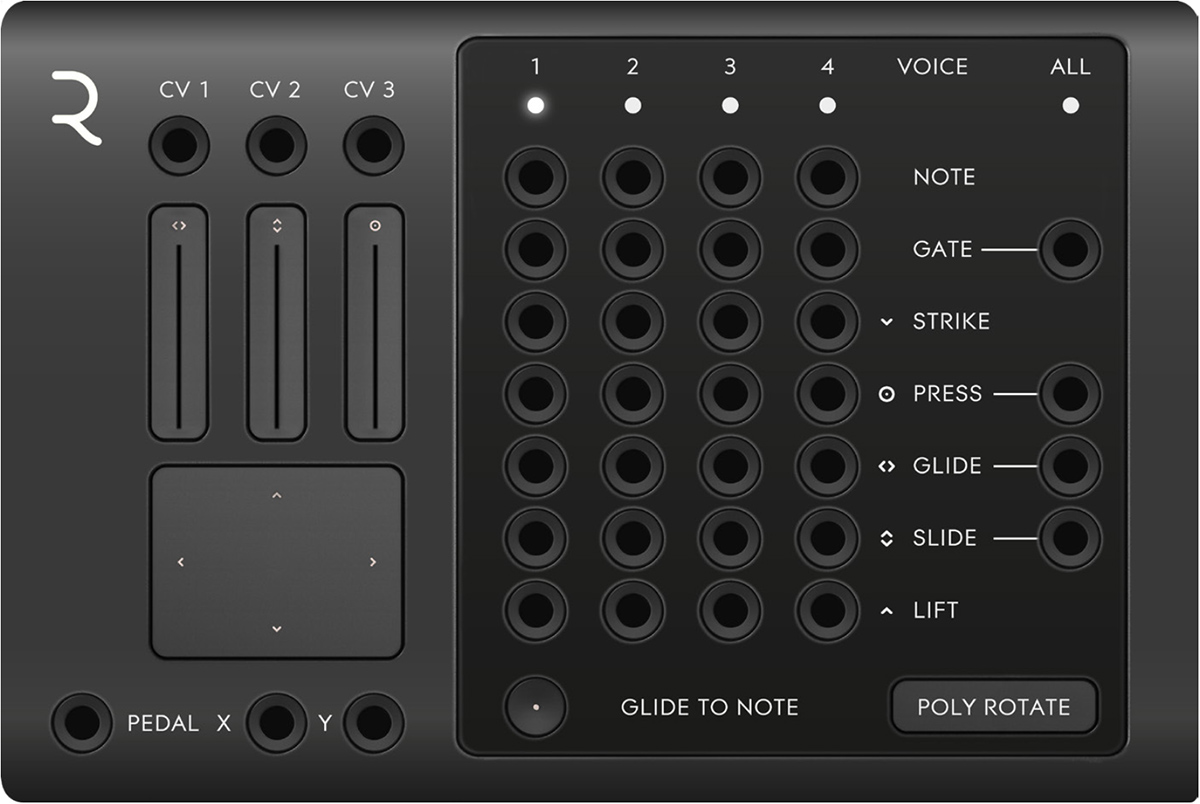
Glide to Note: Turns on and off the RISE’s ability to glide between notes. Turning this parameter OFF does not only disable the gliding zones beneath and above the RISE keybed, but also disables the vibrato (Glide expression) achieved by striking a note and then wiggling your finger sideways on the playing surface. Turning this parameter OFF is advisable for situations where you want the RISE to hit precise chromatic pitch values and don’t want to glide between notes (or want to use the glide to control any other parameter).
Mode: POLY ROTATE: Cyclic voice allocation, a new voice is assigned with each received MIDI note from RISE.
POLY LOWEST: Only one voice channel is triggered as long as only one note is played at the time. If one voice is playing (key is being held, gate is high), the next note added will assign voice channel two and so on.
MONO: In this mode, only channel 1 is triggered by playing RISE.
Indicators
Voice LED 1-4, All: Indicates which voice is currently being triggered by your RISE. All is lit if any voice is active.
Touch Faders 1-3: Indicates the value set on the Touch Faders 1-3. These faders are active in RISE’s MIDI mode (the Power/Mode button on the lower left on RISE is white) and sends out CV ranging from 0 to 5V via the jacks CV1-3 (see more on the CV 1-3 outputs below).
XY Touchpad: Indicates the value set by the XY Touchpad on your RISE. These are connected to the X and Y outputs which send out a corresponding control voltage, ranging from 0 to 5V (see more on the X and Y outputs below).
Outputs
CV 1-3: These jacks send out CV, 0 to 5V, controlled by the Touch Faders 1-3 on your RISE.
Pedal: This jack sends out CV, 0 to 5V, controlled by an expression or sustain pedal connected to the RISE pedal jack.
X and Y: These jacks sends out CV, 0 to 5V, controlled via the XY Touchpad on your RISE.
Voice Outputs 1-4: These are the polyphonic outputs for CV and Gate information. Voice assign set by the Mode parameter will affect the way these output jacks are assigned.
Note: This is the note CV output (1V per octave) for each of the four voices. Connect this output to the main tracking input on your oscillator (such as CV1 on DOEPFER A-110). When the Glide to Note function is activated, this output is not only affected by the played MIDI key but also the RISE channel’s glide.
Gate: These jacks output a logical high signal (5V CV) when receiving a MIDI note on message (a key is struck on your RISE). At MIDI note off (key is released) it instantly falls back to zero (0V CV ). Use this output to connect to a Gate input on an ADSR envelope module.
Strike: This jack outputs 0 to 5V CV reflecting the velocity value (0–127) received from the RISE. The harder you strike the RISE keys, the higher CV output you will get here.
Press: This jack outputs 0 to 5V CV when receiving pressure from the RISE. This means that Modular can receive polyphonic pressure via the RISE module.
Glide: The Glide jack outputs positive or negative CV (1V per octave), corresponding to the horizontal upwards or downwards bend from the note played. The Glide jack is useful as a modulation source especially when the Glide to Note function is set to off.
Slide: The Slide jack outputs CV matching the vertical slide movement performed on your RISE keys.
Lift: This jack outputs CV matching the speed of release on a released key on the RISE. The faster you release a played note, the higher the CV output here will be.
All Gate: The All Gate jack output sums the individual channel gate outputs to a single mono gate output. A logical high signal (5V CV) is sent when receiving a MIDI note on message (a key is struck on your RISE).
All Press: This jack outputs the average pressure CV from all the channels. This means that the more fingers used and the more pressure applied on the RISE’s playing surface, the higher the CV output will be.
All Glide: The All Glide jack outputs positive or negative CV (1V per octave), corresponding to the average horizontal upwards or downwards bend from the notes played.
All Slide: The All Slide jack outputs CV corresponding to the average vertical slide movement performed on your RISE keys. One useful usage of the All Slide output is to control the filter cutoff in a paraphonic patch (a patch with multiple oscillators but only one filter). This makes it possible to control filter sweeps by moving all of your fingers vertically on the RISE.
When interfacing with the Seaboard RISE in Modular through Modular's RISE module, it's good practice to use SLEW LIMITER modules to soften the sudden shifts in CV out, which can otherwise result in audible clicks and undesirable behavior. We recommend that you study the RISE preset patches included among Modular’s presets for inspiration.
The expressiveness of the RISE makes it possible to make really organic sounding patches using for example pressure, strike, glide, slide and lift. The XY Touchpad is really useful when controlling panning and volume at the same time. The Touch Faders 1-3 are useful for example when creating drawbars on an organ or controlling volumes on different channels.
These modules are mainly for interfacing the Softube Modular with your DAW. It features DAW SYNC (MIDI to clock converter), MIDI TO CV (monophonic MIDI to note and gate converter), QUADRAPHONIC MIDI TO CV (four channel, polyphonic MIDI to note and gate converter) and MIDI TO TRIGGER (four MIDI notes to trigger outputs, for triggering of percussive sounds from individual MIDI notes).
This module is an efficient way of getting clock pulses in sync with your DAW. Connect the 16 notes output to click in on your sequencer module and the reset pulse out to reset in for the most common application of this module.

Outputs
1/1: This jack outputs a short pulse on the first beat of each measure.
1/4: This jack outputs a short pulse on each beat (quarter notes).
1/8: This jack outputs a short pulse on each eighth note.
1/16: This jack outputs a short pulse on each sixteenth note.
1/32: This jack outputs a short pulse on each thirty second note.
Reset: Sends out a trigger pulse at the beginning of a bar in the DAW's sequencer.
Run: This jack sends out a high (+5v) signal, when DAW is running.
In Use
Typical use for the DAW SYNC module is to supply clocks for the sequencer modules. Connect for instance 1/16 output to clock in on the sequencer module and the Reset out jack on DAW SYNC to Reset in on the sequencer.
The Run jack can be used together the logic tool module with for example a gate from a sequencer before sending to an envelope GATE IN. In this way, the ADSR gate input is sure not to be held high when DAW is stopped.
Your average workhorse MIDI TO CV converter! This module converts incoming MIDI notes to monophonic CV and Gate outputs. There is also a trigger out for resetting oscillators with each keystroke if that's to your liking. Outputs for the most common performance MIDI controllers such as pitchbend, mod wheel, volume and aftertouch are also provided.

Parameters
MIDI channel: This sets the MIDI TO CV receiving channel. Omni is for receiving on all channels, while numbers 1 to 16 reflects specific MIDI channels.
Transpose: Transpose incoming MIDI notes, plus and minus one or two octaves.
Note Priority: Set the note pitch priority when playing several MIDI notes at once. LOW PRIORITY means lower MIDI notes are selected over higher, while HIGH PRIORITY has the opposite behavior. Last note priority simply means that the last received MIDI note is selected for output note pitch. Note that this only applies for note CV, not velocity CV, since velocity always has the last note priority.
Outputs
Note: 1 volt per octave note CV output. Use this output to connect to your main tracking input on your oscillator (CV1 on A-110 for example).
Pitch Bend: This jack outputs +/- 1V CV (+/- 1 octave) when receiving MIDI pitch bend.
Gate: This jack outputs a logical high signal (5V CV) when receiving a MIDI note on message (a key is stroke on your keyboard) from DAW. At MIDI note off (key is released) it instantly falls back to zero (0V CV).
Use this output to connect to a Gate input on an ADSR envelope module. When receiving several MIDI note on messages, the gate will remain high (at output 5V CV) until last note is released with a MIDI note off message (your key on your keyboard is released).
Mod Wheel: This jack outputs plus 1V CV when receiving MIDI modulation (CC #01).
Trig: This jack outputs a short logical high pulse (5V CV) when receiving a new MIDI note on message from the DAW.
Aftertouch: This jack outputs 0 to 5V CV when receiving a MIDI aftertouch message (channel pressure) from DAW.
Velocity: This jack outputs 0 to 5V CV reflecting MIDI velocity value (0–127). The harder you play on your keyboard, the higher CV output you will get here.
Vol: This jack outputs plus 0–5V CV when receiving MIDI volume (MIDI CC#07).
In Use
Note and Gate outputs can be used to hook up your basic monophonic synthesizer patch, as described in the first tutorial example (see above). Trig Out can be used to reset oscillators and LFOs, or retriggering of ADSR envelopes such as the A-140. Velocity and aftertouch outputs can be used to control filter cutoff modulation or amplitude.
This is a four channel MIDI note to CV and gate converter for creating those four voice polyphonic patches that would cost a fortune in real life.
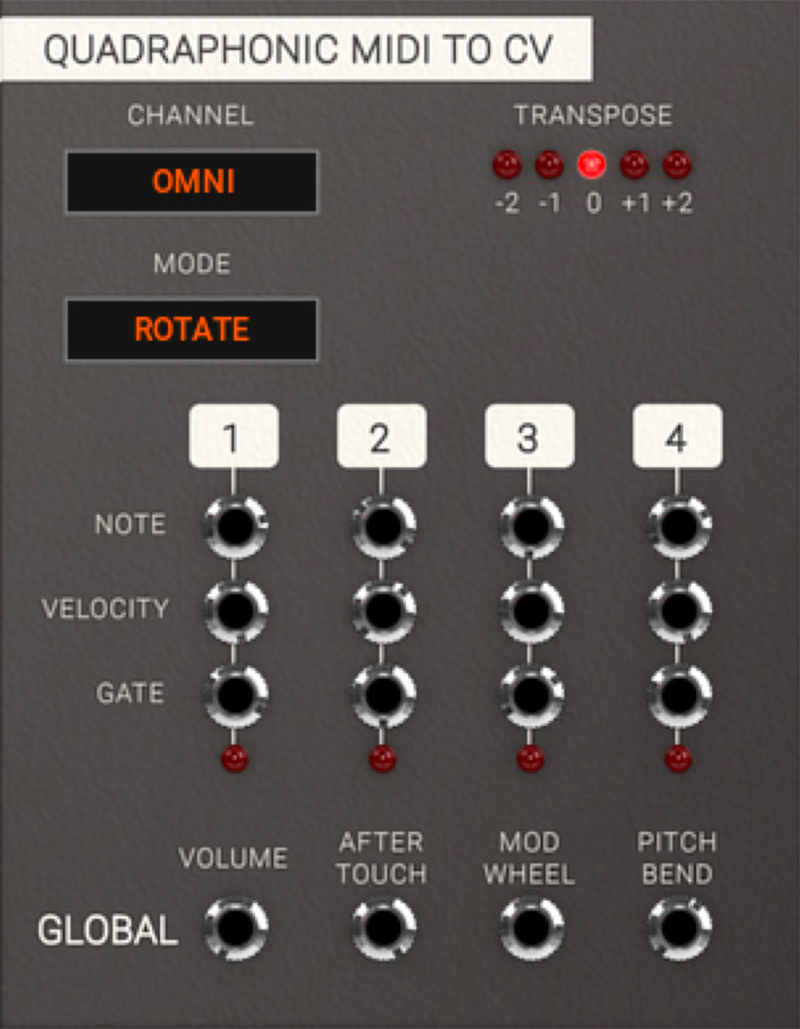
Parameters
Channel: This sets the MIDI TO CV receiving channel. Omni is for receiving on all channels, while numbers 1 to 16 reflect specific MIDI channels.
Transpose: Transpose incoming MIDI notes, plus and minus one or two octaves.
Mode: This sets voice allocation mode. Rotate is cyclic voice allocation, so that a new voice is assigned with every MIDI note received from DAW. LOWEST is voice allocation that assigns only voice channel one as long as only one note is played at a time. If one voice is playing (key is still being held, gate is high), next note added will assign voice channel two and so on.
Outputs
Note: 1 volt per octave note CV output. Use this output to connect to your main tracking input on your oscillator (CV1 on A-110 for example).
Velocity: This jack outputs 0 to 5V CV reflecting MIDI velocity value (0–127). The harder you play on your keyboard, the higher CV output you will get here.
Gate: These jacks output a logical high signal (5V CV) when receiving a MIDI note on message (a key is stroke on your keyboard) from the DAW. At MIDI note off (key is released) it instantly falls back to zero (0V CV). Use this output to connect to a Gate input on an ADSR envelope module.
Volume: This jack outputs plus 1V CV when receiving MIDI volume (MIDI CC #07).
Aftertouch: This jack outputs 0 to 5V CV when receiving MIDI aftertouch message (channel pressure) from DAW.
Mod Wheel: This jack outputs plus 1V CV when receiving MIDI modulation (CC #01).
Pitch Bend: This jack outputs +/- 1V CV (+/- 1 octave) when receiving MIDI pitch bend.
In Use
Connect the Gate outputs to four ADSR modules controlling VCAs and the CV outputs to four VCOs and you have the basics for a four voice synthesizer (see tutorial example "Basic Polyphonic Synthesizer Patch". The QUADRAPHONIC MIDI TO CV can also be used together with the signal tools to create a simple four tone arpeggiator (see for example the preset Seq Melodic Arp Mono).
A four channel MIDI to trigger module, primarily made to trigger percussive sounds off specific MIDI notes. It emits short trigger pulses when a MIDI note is received on the set MIDI channel.
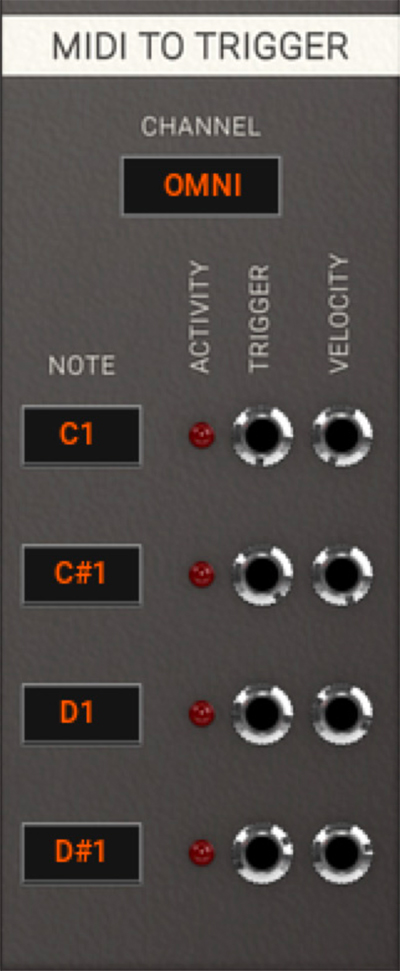
Parameters
Channel: This sets the MIDI TO CV receiving channel. Omni is for receiving on all channels, while numbers 1 to 16 reflect specific MIDI channels.
Note: This is the specific MIDI note which the MIDI to Trigger will receive on this trigger channel. The Activity LEDs will blink when a MIDI note message is received on the corresponding channel.
Outputs
Trigger: This jack outputs a short logical high pulse (5V CV) when receiving a MIDI note on matching the one set on this channel.
Velocity: This jack outputs 0 to 5V CV reflecting MIDI velocity value (0–127). The harder you play on your keyboard, the higher CV output you will get here.
In Use
Set desired receiving MIDI channel and MIDI notes by clicking and dragging. Trigger Out emits short trigger pulses and Velocity outputs last known velocity CV, which is held until next MIDI note is received on the channel.
This category currently only contains the DELAY module, but will be definitely be expanded upon in the future.
This module delays an incoming signal up to 1000 ms (one second).

Parameters
Time: This knob sets the time between 1 ms to 1000 ms (one second).
CV Amount: This knob sets the CV Amount affecting the delayed time of the inputted signal.
Inputs
In: Use this input for the audio or CV you want delayed.
CV: This is input is used for control voltage of delayed time. Closely linked to CV Amount.
Outputs
Out: Output of delayed signal.
In Use
Use the DELAY module to delay any audio or CV signal. Connect it to a mixer and feedback it through a filter to create a classic tape style effect.
Short delays swept in time from a LFO can also be used to create flangers, chorus and such effects. Simple but powerful module.
These are mixers suitable for summing audio (exponential response) and CV (linear response) as well as a polarizing mixer suitable for subtractive mixing, but of course all mixers can be used for either type of signal. All mixer modules have the same controls.
Audio Mixer
Mixer module with an exponential response, making it suitable for mixing audio signals. This mixer uses a dB scale for its knobs, with a maximum gain of 12 dB.

CV Mixer
A no-nonsense CV mixer with a linear response, making it suitable for mixing CV signals. This mixer scales the signal up to 4 times.

Polarizing Mixer
A mixer module with a gain -1 to +1.

Parameters
Volume 1-4: These volume knobs set the amplification of input signal. from -∞ to 12 dB, from 0 to 4x, and from -1 to +1 in the different mixers.
Output Volume: Sets the main output mix amplification. Same range as the input Volume knobs.
Inputs
Input Jacks 1–4: The four input jacks for the signals to be summed.
Outputs
Output: Mixed and amplified output of the four input signals.
Audio Mixer In Use
The AUDIO MIXER is of course preferably used for mixing audio signals, however nothing prevents you from using it for mixing of any kind of signals since there is no DC block on the input or output.
CV Mixer In Use
The CV MIXER is of course preferably used for mixing CV signals, however nothing prevents you from using it for mixing of any kind of signals.
Polarizing Mixer In Use
Use the POLARIZING MIXER for adding and subtracting signals. The POLARIZING MIXER is great to for example mix the outputs of the A-108 to create new and interesting filter characteristics. It is also useful for mixing control voltages or just about any kind of signals.
These are simple 16, 8 and 5 step note sequencers, as well as the BEAT SEQUENCER, a four channel trigger sequencer suitable for triggering percussive elements. All are driven by clock inputs that can be taken from the DAW SYNC module or whatever kind of pulse output.
Classic x0x style sequencer for programming percussive sounds (for example with the HEARTBEAT modules, purchased separately). The sequencer can be looped or not. In LOOP OFF mode the Link Out sends a trig after last step which can be used to link together several sequencers. SWING sets the delay time of every other pulse input.
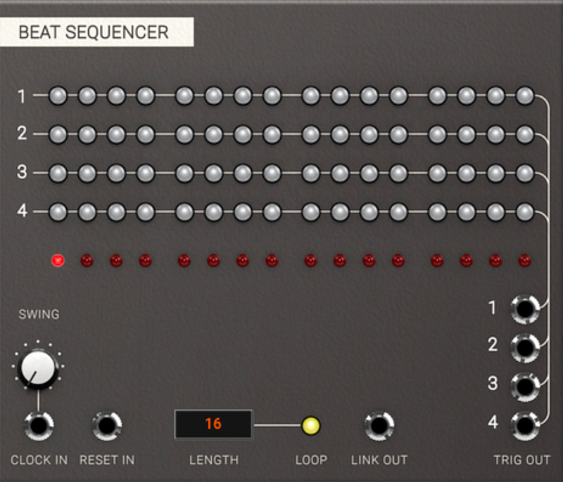
Parameters
Gate/Trig Buttons 1–16: These buttons determine whether or not a trig is outputted on the corresponding output jack.
Indicator LEDs 1–16: These LEDs indicate which steps are active.
Length: This parameter sets the final step played in the sequence. Change the value by clicking on it to add one step at the time, or click and drag to set whatever value between 2 and 16 you want.
Loop: This button determines whether the sequence will loop back after the last step or not. An unlit Loop button means no loop back, and that the Link Out jack sends a pulse after the last step has been reached and one more click has been received at the Clock In jack.
Swing: This knob sets the delay time of each other pulse input. Swing is also dependent on reset pulse in, which can be used for interesting and surprising effects.
Inputs
Clock In: By sending a short pulse or gate into this input jack, the sequencer will progress one step. The most common application of this jack is to connect it to 1/16 Output of the DAW SYNC module.
Reset In: By sending a short pulse or gate into this input jack, the sequencer will instantly reset to the first step. The most common use is to connect it to the Reset Out or 1/1 Output of the DAW SYNC module.
Outputs
Trig Out: This output jack sends short pulses for each activated step. This type of triggers is useful for triggering percussive elements, using for example the HEARTBEAT modules.
Link Out: This jack outputs a short pulse after the last step has been reached when the module isn't in LOOPED mode and the sequencer receives another clock in. Use it to reset the next sequencer you want to link in order to expand your sequence beyond 16 steps.
In Use
Patch Trig Outs to Trig Ins on HEARTBEAT modules or to Gate In on the ADSR envelope you want to trigger.
To create accents, use one channel to control an envelope module and a VCA and run your sounds through that to control their dynamics. Swing means that every second clock pulse gets delayed, so if you for example use the 16th notes output from DAW SYNC to feed the clock input on the sequencer, only the steps with equal numbers (2,4, 6 etc) will be affected. This becomes apparent when programming pulses on all 16 steps.
Sequencer 16, Sequencer 8 and Penta Sequenza
Classic step sequencers with CV Out and Gate Out. Multiple gates after each other extends the gate output over several steps. A separate trig channel is provided as well as chromatically quantized CV scaling. Sequences can be looped or not.
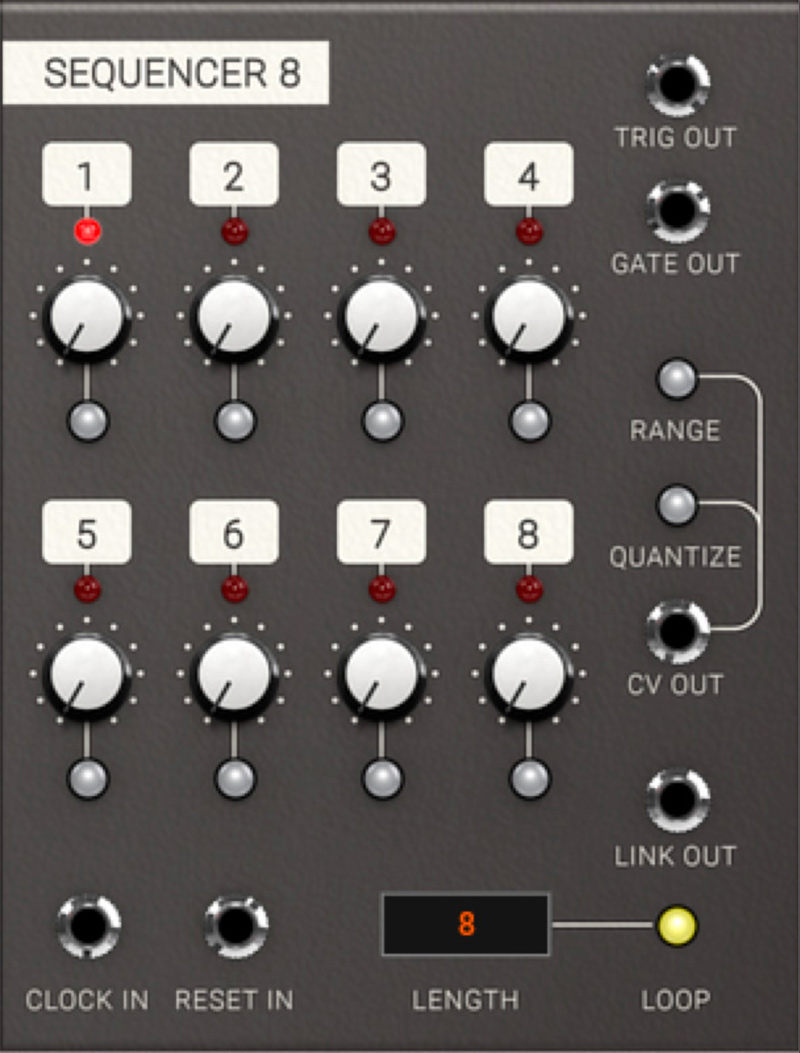
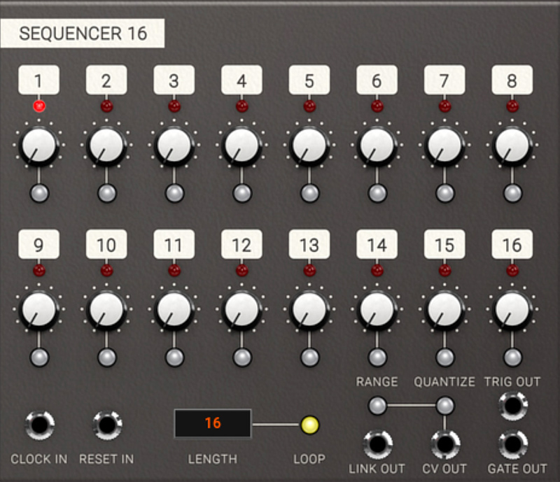
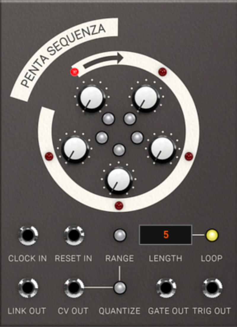
Parameters
Indicator LEDs 1–16: These LEDs indicate which steps are active..
CV Knobs 1–16: These knobs set the amount of output CV at the CV Out jack when the corresponding step is active. CV AMOUNT is shown in volts down in the value display in the lower left side of the plug-in.
Gate/Trig Buttons 1–16: These buttons determine whether a gate and a trig is outputted on the Gate Out and Trig Out jacks when the corresponding step is active. Several consecutive gates creates legato notes, but separate triggers.
Length: This parameter sets the length of the sequence. Change the value by clicking on it to add one step at a time, or click and drag to set the value between 2 and 16.
Loop: This button determines whether the sequence will loop after last step or not. If Loop is OFF, Link Out will send a pulse after a completed sequence.
Range: This button switches the CV Out between limited range (1 octave) and full range (5 octaves). When activated, full clockwise position of the CV knobs will correspond to a one octave jump.
Quantize: When activated, the CV Out jack will be quantized to the nearest semi tone. Use this function when using the sequencer to program note information.
Inputs
Clock In: By sending a short pulse or gate into Clock In, the sequencer will progress one step. The most common application is to connect the 1/16 output of the DAW SYNC module to the Clock In.
Reset In: Reset the sequencer step by sending a pulse to this jack. Most common application is to connect the Reset Out or 1/1 output of the DAW SYNC module to the Reset In.
Outputs
Trig Out: Sends short pulses for each activated step that the sequencer passes when clocked. These kind of triggers are useful for triggering percussive elements, such as the HEARTBEAT modules.
CV Out: Sends the programmed CV for each step. Range button and Quantize button affects the output CV information (see above).
Gate Out: Sends a gate for each activated step that the sequencer passes when clocked. Several consecutive gates creates a combined long gate (legato).
Link Out: This jack outputs a short pulse after the last step has been reached when the module isn't in looped mode and the sequencer receives another clock in. Use it to reset the next sequencer you want to link in order to expand your sequence beyond 16 steps.
In Use
When linking more than one sequencer, use LOOP OFF mode, where the Link Out sends a trig after last step, which can be used to link together several sequencers. Use the Link Out trigger to reset the next sequencer, also in LOOP OFF mode, clocked from same clock source (see "Linking Multiple Sequencers Patch"). The sequencer can be used not only for note information, but also as a programmable modulation source.
The PENTA SEQUENZA is ideal for use as a quirky modulation sequencer. Using an odd number of stages for running a more traditional sequencer like the 16 step sequencer in parallel can create some really interesting polyrhythmic effects.
The Utility Modules is a collection of simple useful modules, such as a simple SINCE OSCILLATOR, an ENVELOPE FOLLOWER, MULTIPLE, OFFSET, SLEW LIMITER, CLOCK DIVIDER, LOGIC and SIGNAL TOOL, as well as SAMPLE & HOLD and CV-controllable switches.
This is a simple and mathematically correct sine oscillator with perfect tracking. It was originally created for testing purposes in the early stages of the development of Softube Modular.

Parameters
Pitch: This knobs sets pitch offset ranging from 0.1 Hz up to 10 kHz. The 12 o'clock position is a C at 64 Hz (this position is easily reached by alt clicking on the pitch knob).
Inputs
CV in: This is a normal 1 V/octave tracking input jack. Connect note CV out from the MIDI TO CV module for musical use of the sine oscillator.
Sync: This is a reset input jack for syncing purposes. Similar to hard sync on other oscillators.
Outputs
Out: This is the main output jack.
In Use
The sine oscillator is great as a space efficient LFO or as FM operator in use with for example the INTELLIJEL RUBICON.
This module can be used to generate control voltages from audio sources, but also as a simple ASR envelope.

Parameters
Attack: This knob controls how quickly the ENVELOPE FOLLOWER will react to a rising edge amplitude change.
Release: This knob controls how fast the ENVELOPE FOLLOWER will react to a falling edge amplitude change.
Inputs
In: This is the input jack. Connect it to audio or gate signal from your MIDI TO CV module if you’re using it as a regular envelope.
Outputs
Out: This is the output jack. Resulting CV from the ENVELOPE FOLLOWER is output here.
In Use
Use the ENVELOPE FOLLOWER to, for example, create an auto-wah by letting audio controlling a low pass filter. The ENVELOPE FOLLOWER can also be used as a simple ASR (Attack, Sustain, Release) envelope if it's triggered with a gate signal.
This module multiples the incoming signal to four identical outputs.

Inputs
In: The input signal.
Outputs
Out 1 - 4: Four identical outputs for distribution of the input signal to four different sources.
In Use
The MULTIPLE can be seen as quite unnecessary in the Softube Modular since all outputs can be routed to any number of inputs, but it can be used for esthetic reasons, just to keep your patch tidy. It is also true to how many real life Eurorack modular systems look like when not using “stackables” (stackable cables).
The OFFSET module can be used both as a static CV source, but of course also to offset the input CV.

Parameters
Offset: This knobs sets offset between -10V through 0V to a maximum of 10V
Inputs
In: Input signal to be offset goes here.
Outputs
Out: This is the sum of the input signal and the set offset. If a signal is not inserted at input, output will directly correspond to set offset.
In Use
Offsets can be used to set level threshold, for instance with the A>B function in signal tool. Offsets can also be used to control several CV controllable parameters at the same time and linked to a performance knob for “morph-type” operations.
More or less the same as OFFSET, but with four channels contained within the same module to save space.

Parameters
Offset 1 - 4: These knobs set the offsets of the four channels between -10V through 0V to a maximum of 10V.
Inputs
In 1 - 4: Input signals to be offset goes here.
Outputs
Out 1 - 4: These jacks output the sums of the input signals and the set offsets. If signals are not inserted at input, the outputs will directly correspond to set offset.
In Use
More or less the same areas of use as the single offset module.
The SAMPLE AND HOLD module listens to an incoming signal and samples the control voltage at a time set by the incoming trig pulse at the trigger input.

Inputs
In: Input signal to be sampled from. Can be any signal imaginable.
Trigger In: Pulse input. Input signal at the In jack is sampled at rising edge of a pulse.
Outputs
Out: Outputs the sampled and held CV signal. CV is held until next trigger pulse is presented at the trigger input.
In Use
The classic application of sample and hold is to create something called a “stepped random control voltage”. By sampling white noise with a steady stream of pulse (preferably from a LFO) a “stepped random control voltage” is achieved, creating a sound famililar from robots and droids of the sci-fi flicks of the 1970ies. Another application is to trigger it at high frequency to create a bitcrusher (look at the preset "Bitcrusher" in the Modular FX for examples of this).
A slew limiter is a device that smoothes an incoming signal, limiting the maximum rate of change of the output voltage per unit of time. It is often called lag generator. It creates a glide or portamento when applied to a note CV signal.

Parameters
Time: This knob sets the slew time from 0 to 10 seconds.
Inputs
In: Input CV signal here is smoothed out.
Outputs
Out: CV output of the Slew limiter.
In Use
Can be used on Note CV to create portamento or glide effects. Random bursts of white noise can be filtered into slowly evolving random CV changes.
This module outputs a clock pulse for every x pulses it receives. Use for example the /3 output to trigger an output pulse for each third incoming pulse.

Parameters
Divide: Sets the division of the clock on the Out output.
Inputs
In: Clock pulse input.
Reset: Reset pulse output and all internal counters and clocks.
CV: CV control the clock division of the Out jack.
Outputs
Out: This is the programmable division output. It outputs pulses divided between 2 and 32 times and are affected by the Divide offset knob and the CV division input.
/2: Outputs a pulse for every 2nd input pulse.
/3: Outputs a pulse for every 3rd input pulse.
/4: Outputs a pulse for every 4th input pulse.
/8: Outputs a pulse for every 8th input pulse.
/16: Outputs a pulse for every 16th input pulse.
In Use
Clock division means that clock pulses arriving at the input are counted and output pulse will be generated for example every 16th pulse at the /16 output. The division module is most commonly used as clock divider, but can of course also be used as a suboscillator if connected with a pulse output of an oscillator.
This module is used to perform simple logical operations on DC signals where signals over 2.5V equals a logical high state (1) and below 2.5V equals a logical low state (0). The module has two inputs with inverting logical outputs. The two inputs are compared in logical function truth tables and each logical function has its own output.

Inputs
In A: Signal input of channel A: the first operand.
In B: Signal Input of channel B: the second operand.
Outputs
Inv A: Inverted logical output of channel A. Output is high for inputs below 2.5 V, as indicated by the LED.
Inv B: Inverted logical output of channel B. Output is high for inputs below 2.5 V, as indicated by the LED.
AND: Output jack for logical AND function. This output is high when both channel A and channel B inputs are high.
NAND: Inverted function of the AND output jack.
OR: Output jack for logical OR function. This output is high when either channel A or channel B, or both inputs are high.
XOR: Output jack for logical XOR (exclusive OR) function. This output is high only when either channel A or channel B input are high.
NOR: Inverted function of the OR output jack.
In Use
To make a sequencer stop mid sequence, you can connect the DAW SYNC's Run signal to A, and Gate Out from the sequencer to B, and use the AND output to control an audio source. This means that both the Gate Out and Run must be active for AND output to become active.
This module acts as a toolbox for continuous CV signals and does not differentiate between logic high and low like the LOGIC TOOL (see above).

Inputs
In A: Signal input of channel A, the first operand.
In B: Signal input of channel B, the second operand.
Outputs
Neg. A: Negative output of channel A. An input of for example 2V will give an output of -2V.
Neg. B: Negative output of channel B.
ABS A: Absolute output of channel A. An input of 2V and a signal of -2V will give same output of 2V.
ABS B: Absolute output of channel B.
Max: Outputs the maximum of channel A and B. If channel A has 2.5V and channel B has 2V Max will output 2.5V.
Min: Outputs the minimum of channel A and B. If channel A has 2.5V and channel B has 2V Min will output 2V.
A+B: Outputs the sum of channel A and B.
A-B: Outputs the difference of channel A and B.
A>B: Outputs logical high (5V) when A level exceeds the level of B.
Clip: Clips channel A at channel B's input level.
In Use
The signal tool has many uses, for example, it can be used to compare levels on incoming audio on Modular FX to create faux compressor type patches.
This CV controllable switch can be used to direct a CV source or audio signal to any of four different destinations.

Parameters
Select: Select which of the four outputs that will be connected to the input.
LEDs: Indicate which of the four outputs is active.
Inputs
In: Input jack of the switch.
CV: CV input for controlling the connected output.
Outputs
Out 1 - 4: Output jacks.
In Use
The switch 1 to 4 can have a lot of uses such as creating interesting modulation routes or pseudo-sequenced noises.
CV controllable switch that can be used to select one of the four connected CV or audio sources and send it to a set destination.

Parameters
LEDs: Indicate which of the four inputs is active.
Select: This knob is the offset for which of the four inputs will be connected to the output.
Inputs
In 1- 4: Input jacks of the switch.
CV: CV input for controlling the connected input to the output.
Outputs
Out: The output jacks of the Switch 4 to 1 module.
In Use
SWITCH 4 TO 1 can be used to select modulation routes or change distributed clock divisions for your sequencer. On some of the presets for the Modular FX, the SWITCH 4 TO 1 module is used to turn on and off an effect, guitar-pedal style.
Two channel, CV controllable panning module that can be used to place a mono signal in a stereo mix, or to use as an A/B switch. The panning curve uses a constant power pan law with a +3 dB boost at the edges.

Parameters
[pan indicator LEDs]: Indicates the panning balance for the left and right outputs of channel 1 and channel 2.
Pan knob: Sets the Pan offset on its respective channel. The overall pan amount is determined by the CV input and the Pan knob.
Inputs
In: Audio input jack of channel 1 and channel 2.
CV: CV input for external control of the pan of channel 1 and channel 2.
Outputs
L, R: The outputs of channel 1 and 2.
1+2: These are the combined outputs of channel 1 and 2. L outputs from channel 1 and 2 are mixed together in output L 1+2, and R outputs from both channels are mixed together in output R 1+2.
Dual Pan in use
The DUAL PAN module can be used to manually or automatically pan a mono signal in a stereo mix. A typical example would be two percussive sounds that the user wants to place individually in the stereo image. The summed output, 1+2, can then be used to add the two stereo panned signals together.
You can also use the DUAL PAN as an A/B switch to send a CV or audio signal to different inputs.
Two channel, CV controllable crossfade module that can be used to mix two mono signals with a CV controllable balance input. Crossfade curve response is linear with a -6 dB dip in the middle.

Parameters
[crossfade indicator LEDs]: Indicates the crossfade balance for the LEFT and RIGHT inputs of channel 1 and channel 2
X-fade knob: Sets the crossfade offset on its respective channel. The overall crossfade amount is determined by the CV input and the X-fade knob.
Inputs
L, R: Input jacks for the two signals to which the crossfade is applied.
CV: CV input for external control of the crossfade function.
Outputs
Out: The outputs of channel 1 and 2.
1+2: This is the combined output of channel 1 and 2.
Dual X-Fade in use
The DUAL X-FADE module can be used for mixing different waveforms together, switching between sources, or modulating sources.
A typical use case would be an automated fade between two signals. Cross-fades can for be used as a pseudo-low pass filter when fading between outputs from the same oscillator, for example a sine or triangle on input 1, and saw or square on input 2. Then use an envelope or LFO to “sweep the filter” by patching the CV input.
The Utility Quantizer module looks at input CV and outputs a quantized CV based on either a chromatic scale (top section) or a user definable scale (set on the bottom section). Chromatic scale means that each octave of 1V each is divided into 12 equal parts that corresponds to a chromatic 12 tone scale on a standard black and white keyboard.

Parameters
C to B buttons: In the bottom section of the Quantizer the user definable scale is found. Each button active (on) represent a note part of your user definable scale.
Inputs
Chromatic CV in: This is the CV input that you want quantized to a chromatic 12 note scale.
User Definable CV in: CV input for the user definable scale part. Input any control voltage here that you want to be quantized to your custom scale.
Outputs
Chromatic CV out: This is the CV output of the 12 note chromatically quantized voltage.
User Definable CV out: CV output for the user definable CV scale. The output CV here is quantized to the notes active via the C to B buttons.
In Use
The Utility Quantizer is great fun! Use it for example to extract musical material out of the random output of the A-118 Noise module. Or apply it to any kind of sequencer in order to stay in the right (customized) key when you transpose the sequence.
The MIDI Step Sequencer is a sequencer containing 64 programmable steps. Each step can contain a note on pitch or rest, tie and accent. The inspiration comes from the legendary Roland SH-101 and TB-303 step sequencers, but with some twists of our own.
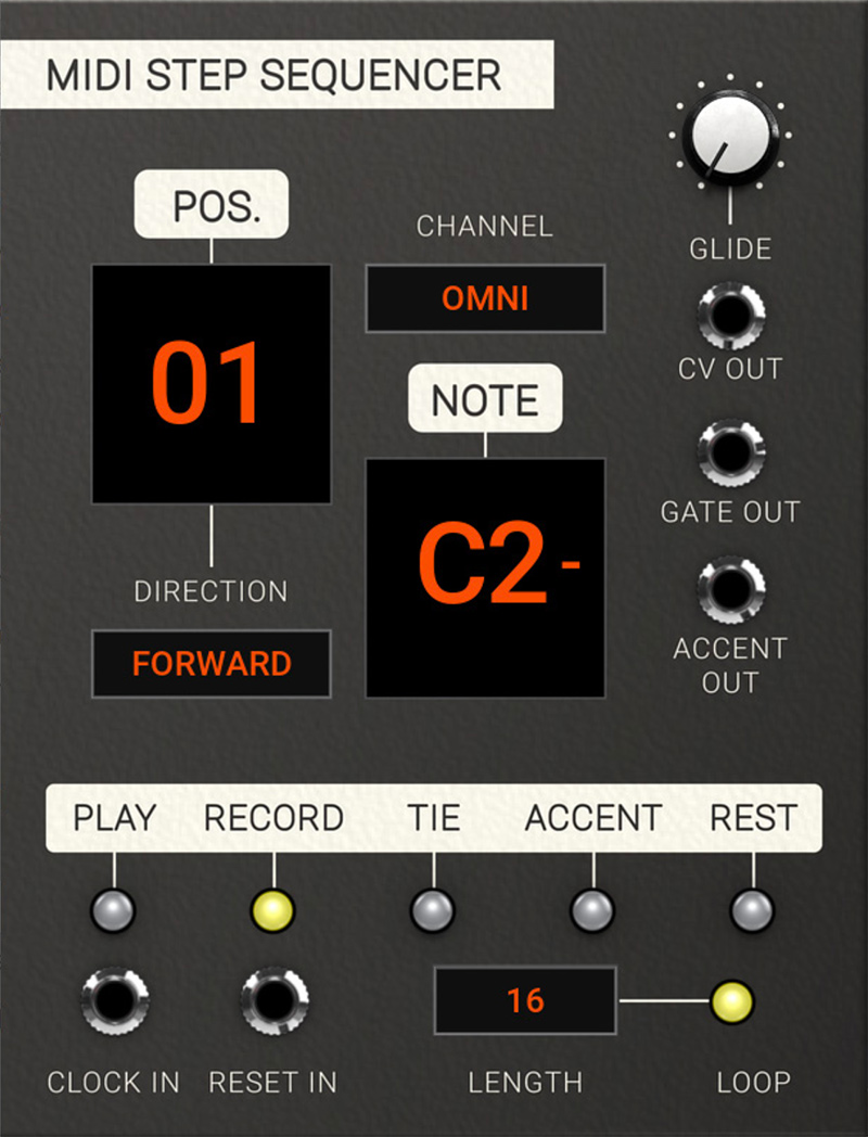
Getting started
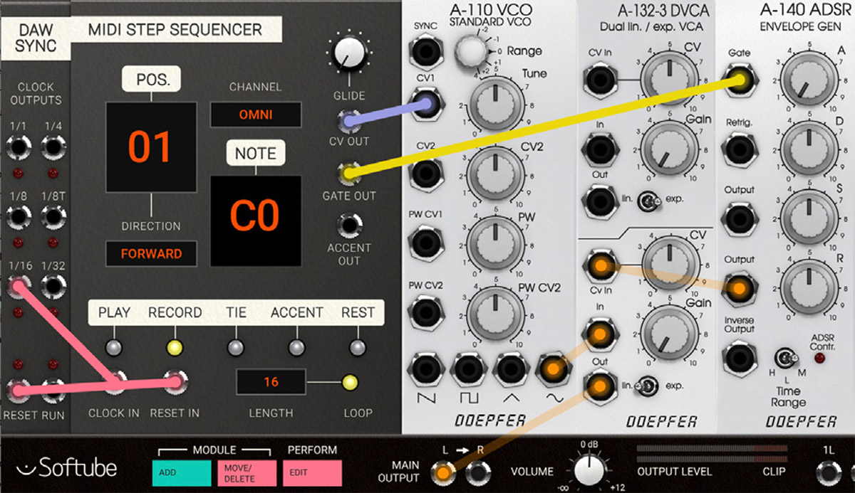
1. Let's program and play back a simple sequence! Let's start off by adding and connecting the following modules as pictured above.
2. The MIDI Step Sequencer by default starts in record mode. This means that any MIDI notes played into the MIDI Step Sequencer will be recording into its memory and it will progress it one step for each note. Let's try inserting an C4 note by playing it on a MIDI keyboard connected to your DAW sending MIDI on the same channel as Modular is situated.
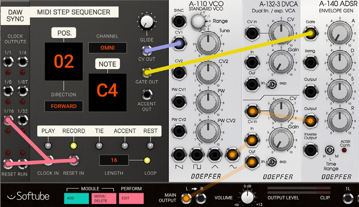
3. Dang! You played a C4 and hopefully also heard this reflected by the simple VCOVCA-envelope patch. You can also see that the step sequencer automatically progressed to position 2.
4. Let's add a rest on position 2, meaning that this step will be silent. Click on the Rest button to switch rest “on” and the sequencer will progress to position 3.
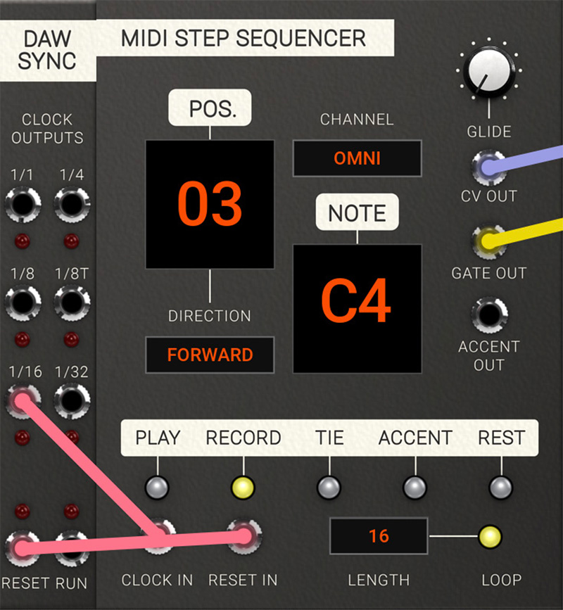
5. OK, now let's add a longer note linking together positions 3 and 4. Now let's first add a another C4 on position 3 by playing a note again.
6. Dang! Now, when on step 4 (the position indicator showing 4), click on the tie button which lits up and a T is lit in the lower part of the Note display. Then play another C4 to extend the C4 note from step position 3.
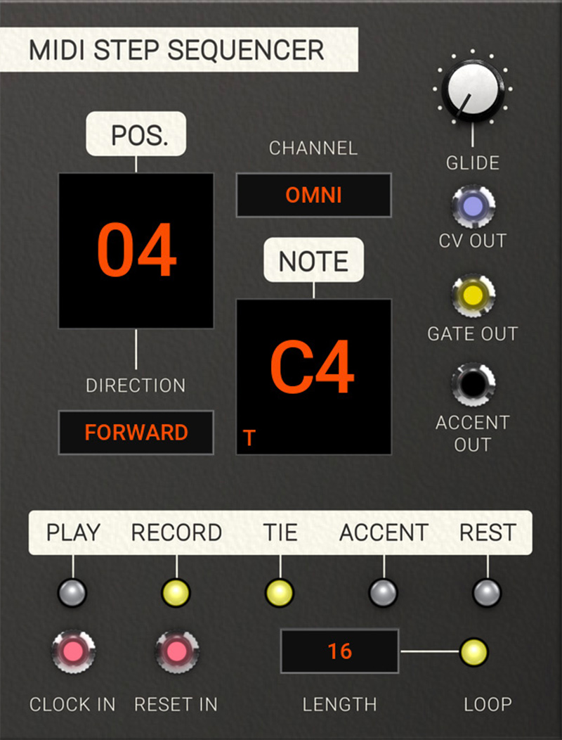
7. Now let's listen back. Click on the play mode button and the MIDI step sequencer will now be ready to step through the programmed steps when clock-information from the DAW SYNC module is fed to its clock input. Start your DAW and you'll hear and see your sequence of the two C4 notes being played back.
Now experiment with the other parameters – try inserting tie, accents and rest into your programmed sequence by clicking on record again, and scroll back and forth in your sequence by clicking on the position window (you can use both click or click+drag). Accent is a trigger out pulse for a second accent envelope or another external event (more details on accent below).
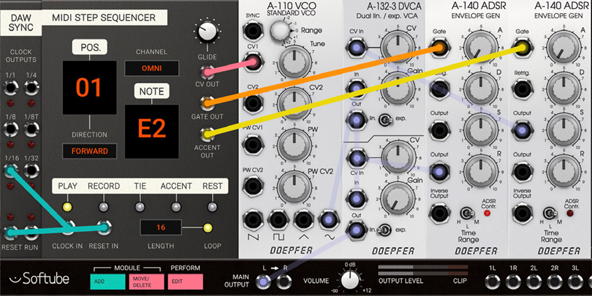
Parameters
Glide: This is the amount of glide time added to the output CV when to steps are tied together with the tie function (see further description below). This creates a bend between notes of different pitch.
Pos: This is the indicator and parameter for current position / step. In record mode this parameter can be used with click and drag in order to set current position to write to. Also, clicking on the display will progress it one step at a time. In play mode this parameter will only display played back position and is not clickable.
Channel: This parameter set the MIDI at which the MIDI Step Sequencer receives its MIDI note information. Default channel is omni which is MIDI notes received on all channels simultaneously.
Direction: This parameter tell the sequencer in which order the steps will be played back:
forward – Sequencer playback start from position one and progresses forwards until the last position (corresponds to Length) is reached, or until a reset pulse is received at the Reset in jack.
backward – Sequencer playback start from last position (corresponds to Length) and progresses backwards until the first position is reached. When a reset pulse is received at the Reset in jack, the sequencer will revert to last position.
pingpong – Sequencer playback start from position one and progresses forwards until the last position (corresponds to Length) is reached. When last position is reached another clock-pulse at the Clock in jack will progress the sequencer backwards until first position and then start over. When a reset pulse is received at the Reset in jack, the sequencer will start from first position.
random – Sequencer playback position is a random step within the loop length. When a reset pulse is received at the Reset in jack another random position is recalled.
Play / Rec: These buttons changes between Playback mode and Record mode. In Playback mode, the MIDI Step Sequencer is waiting for clock triggers to enter the clock in jack in order to progress forward. In Record mode, the MIDI Step Sequencer is expecting the user to enter MIDI note information on the selected MIDI channel. In this mode, step position can also be scrubbed back and forth by clicking or clicking+dragging on the position display.
Tie: When this button is activated, the previous step and current step will be tied together – this is called legato in musical language. When two steps are tied together the glide buffer is activated making it possible to “glide” from one note to another (also known as “glissando”). Tie is indicated written in the MIDI Step Sequencer memory by appearing as a “T” shown in the display on the steps it is written when being played back.
Accent: When this button is activated, a short trigger pulse is sent out of the Accent out jack. This pulse can for example be used to trigger an envelope for extra punch in your basspatch. Accent is indicated written in the MIDI Step Sequencer memory by appearing as a “A” shown in the display on the steps it is written when played back.
Rest: When this button is turned from off to on, a rest is entered into memory and the MIDI Step Sequencer will step forward to the next position (a rest is written into memory). Note that this is only for when the Rest button is turned from off to on, not the other way around. A rest entered into the memory of the MIDI Step Sequencer means that this step has a gate output value set to zero (in effect will not trigger any envelopes). When played back, the Rest is indicated written in the MIDI Step memory by appearing as a “R” shown in the display.
Note that Tie, Accent and Rest information previously inserted into your sequence step in discarded when entering a new note value into the same step of the sequence via MIDI.
Indicators
Pos display: In this display window the currently played back position.
Note display: This display shows information on the played back note related to the current position. Note is represented by a letter (C-B) and with an octave the suffix. A lit up “#” sign indicates a sharp note and a “-” sign is used in addition to show the two lowest octaves (C-2 to C0). The “T”,”A” and “R” indicators are lit to indicate an added Tie, Accent or Rest in a step position.
Inputs
Clock in: A pulse received at this jack will progress the MIDI Step Sequencer one step forward when in play mode.
Reset in: A pulse received at this jack will reset the MIDI Step Sequencer to the start position when in play mode. Note that start position will be different depending on which play mode (forward, backward, pingpong or random) is currently being used.
Outputs
CV out: This jack outputs the note CV information on the currently selected step. CV notes values are discrete with the exception of notes linked together with ties where glide is applied.
Gate out: This jack output a gate when a note is playing. If notes on adjacent steps are linked together with ties, the gate will remain high until the next step not containing a tie.
Accent out: This jack will output a trigger when an accent is activated on a step.
The MIDI Step Sequencer module in use
The MIDI Step sequencer is of course great to use a no-frills programmed step-sequencer in the vein of the Roland-sequencers that inspired it, but here's a few more interesting applications to use it:
1. Pseudo arpeggiator: Use the MIDI Step Sequencer as a “programmed” arpeggiator, in this case a sequence that is being triggered by the timing information from the beat sequencer and transposed from the MIDI-to-CV module.
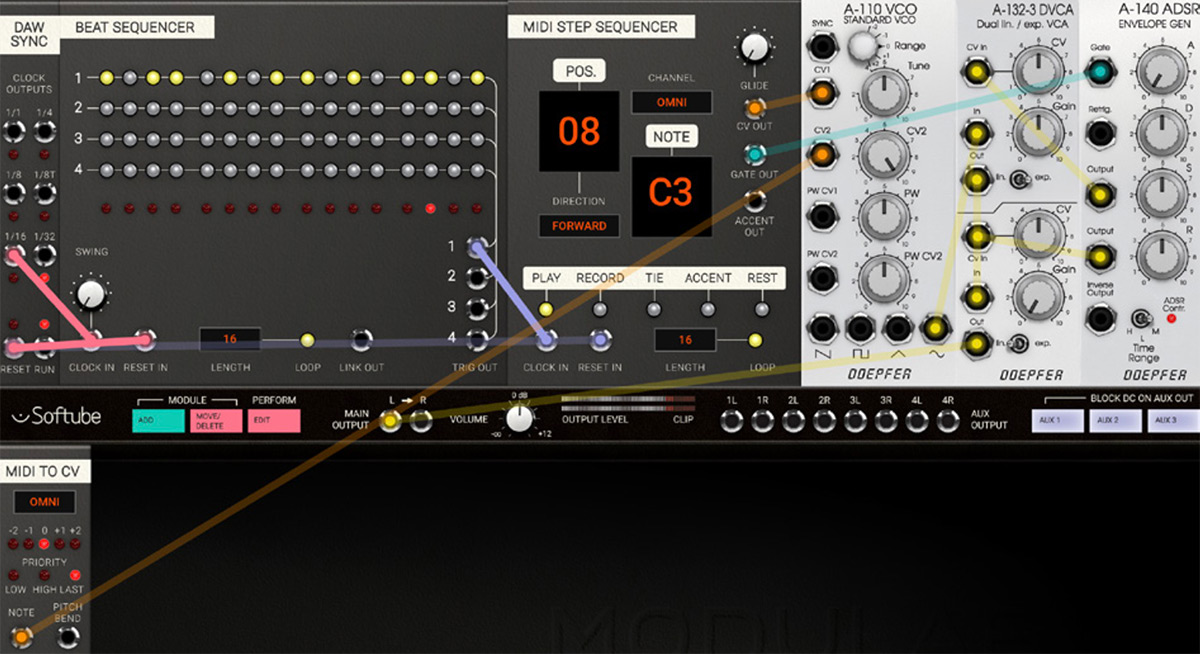
2. Polyphonic offset: Use a MIDI Step Sequencer as programmed polyphonic offset to your incoming notes per voice in a polyphonic patch. This can be observed in detail in the preset called “Quad Ring Seq” (required Mutable Instruments Rings):
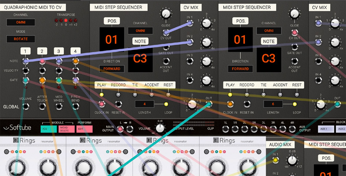
3. Quantized Random Memory: Insert a programmed scale of your choice into the MIDI Step Sequencer and use that as a random source of pitch CV to accompany your melody line. Fun and creative!
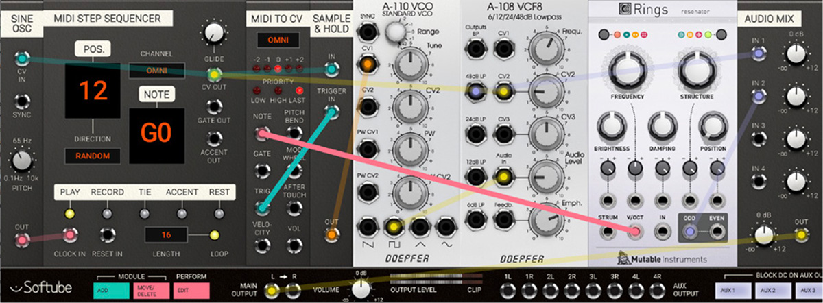
4. Accented Duophony: Use the MIDI Step Sequencer's accent functionality to trigger a second oscillator's sample and hold and separate envelope. In this way a neat musical “cat-and-mouse- chase” is created between the oscillators where one mirrors the other every now and then. Great for creating sequences that alternates between unison and harmonies. An example is found in the preset called “MIDI Step Duo”.
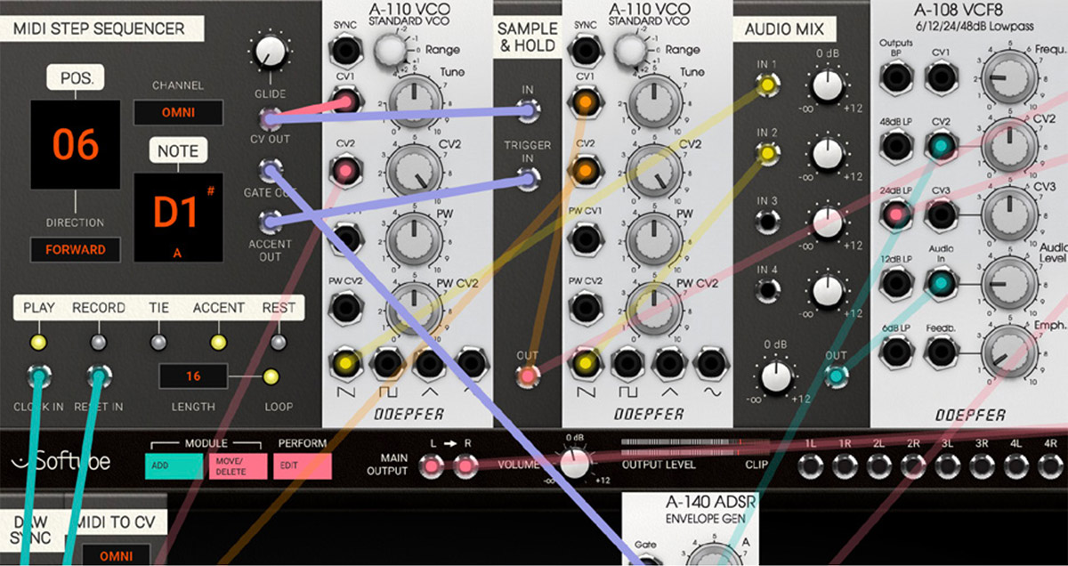
Oscar Öberg – Concept, modeling, sound design
Kristofer Ulfves – Concept, marketing, presets, user's guide
Björn Rödseth, Kim Larsson – Modeling
Arvid Rosén – Modeling and validation
Patrik Holmström – Graphics programming
Niklas Odelholm – Graphic design, programming, model validation
Paul Shyrinskykh – Quality assurance
Torsten Gatu – Programming
Henrik Andersson Vogel – Marketing, user's guide
Danjel van Tijn – Hardware design and model validation
Dieter Doepfer – Hardware design and model validation
Chris Assall – Model validation
Kabuki – Presets